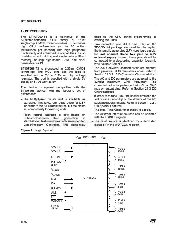
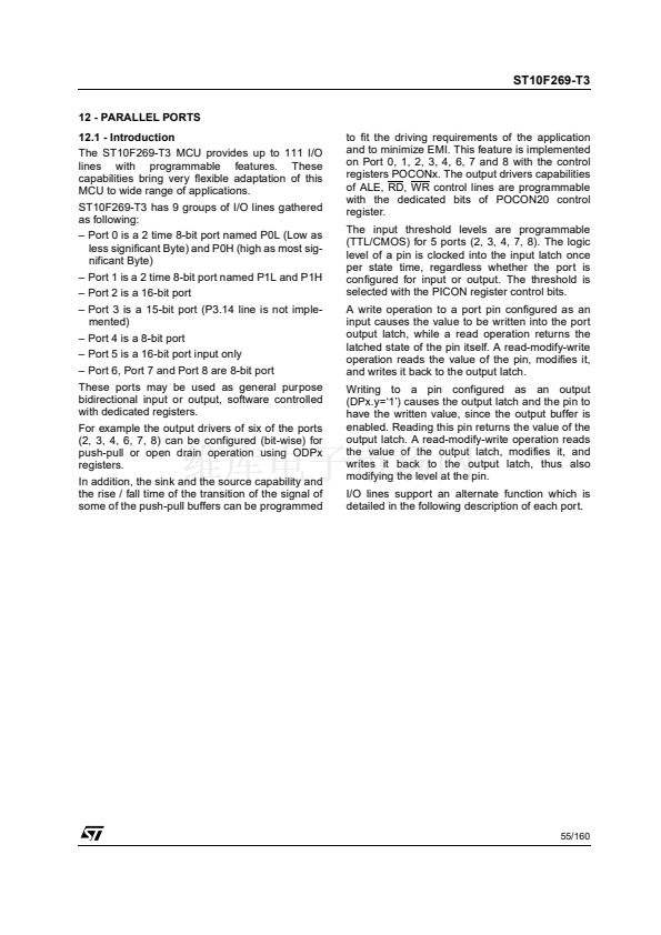
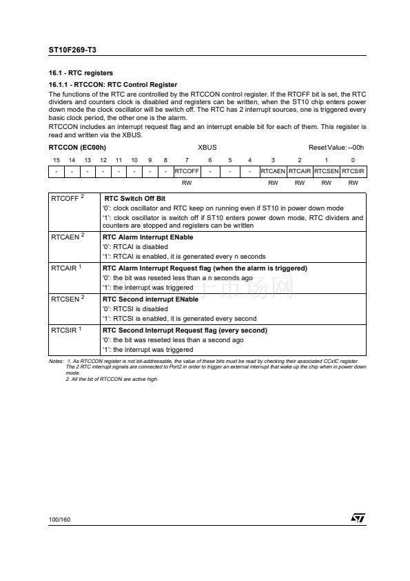
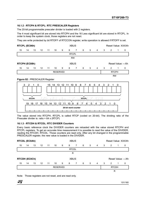
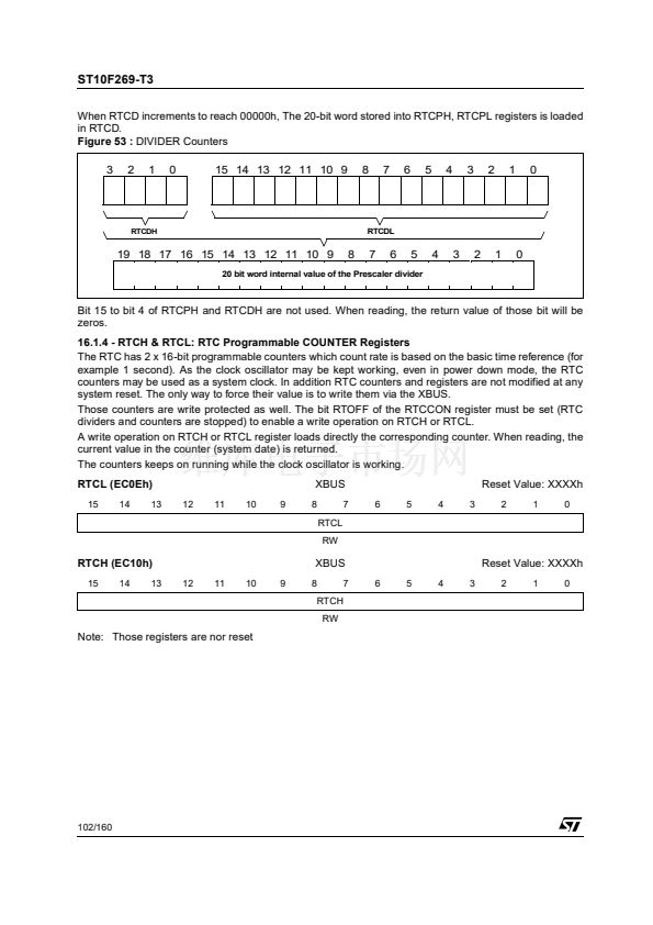
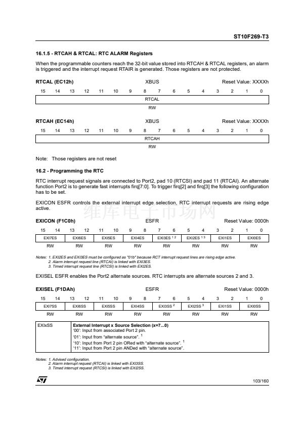
ST10F269-T3
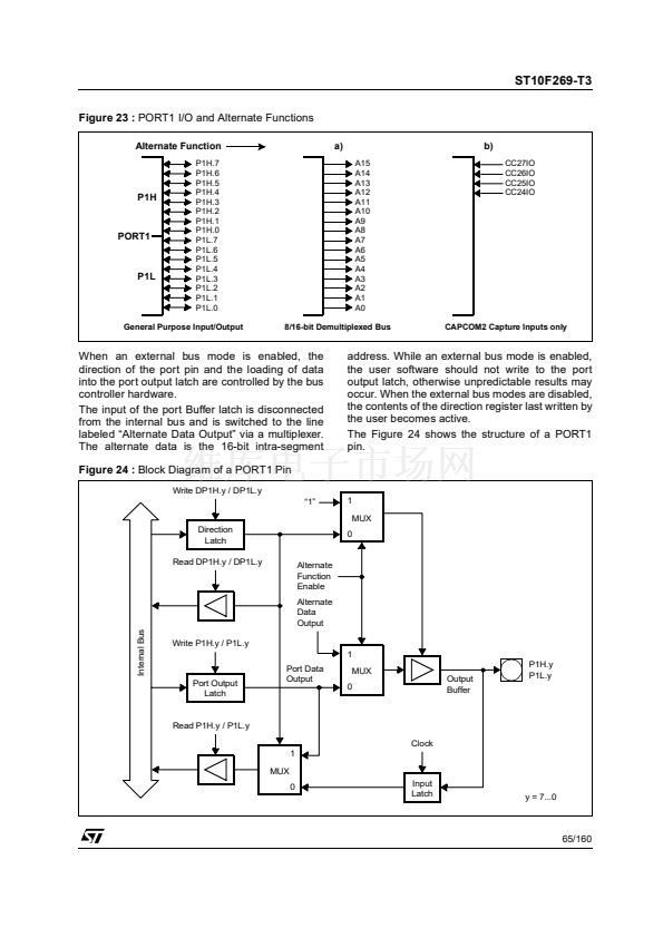
The direction of the pin should be set to output by
the user, otherwise the pin will be in the
high-impedance state and will not reflect the state
of the output latch.
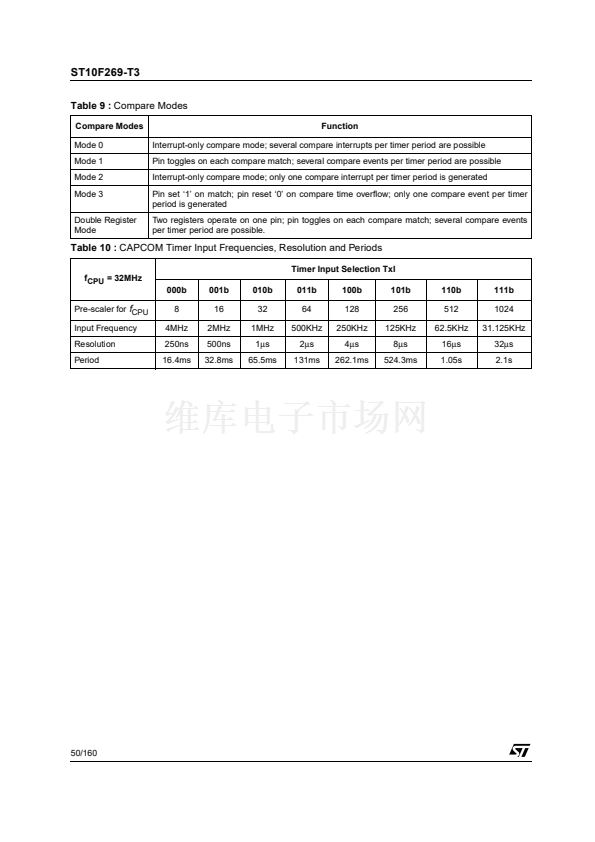
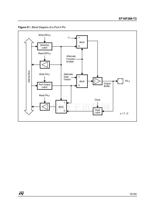
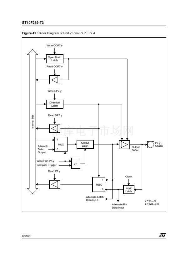
As can be seen from the port structure in Figure
26, the user software always has free access to
the port pin even when it is used as a compare
output. This is useful for setting up the initial level
of the pin when using compare mode 1 or the
double-register mode. In these modes, unlike in
compare mode 3, the pin is not set to a specific
value when a compare match occurs, but is
toggled instead.
When the user wants to write to the port pin at the
same time a compare trigger tries to clock the
output latch, the write operation of the user
software has priority. Each time a CPU write
access to the port output latch occurs, the input
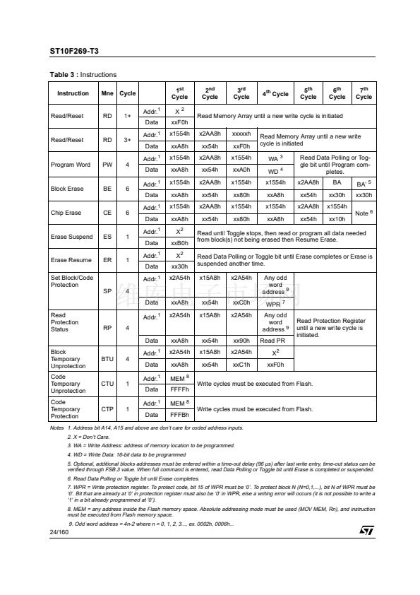
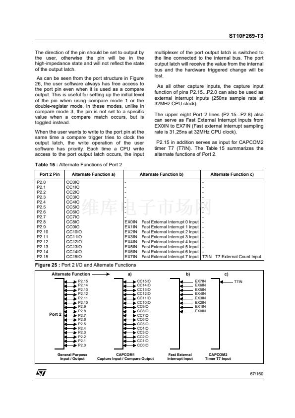
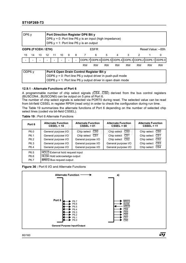
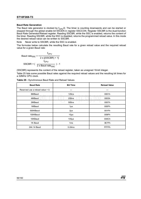
Table 15 :
Alternate Functions of Port 2
Port 2 Pin
P2.0
P2.1
P2.2
P2.3
P2.4
P2.5
P2.6
P2.7
P2.8
P2.9
P2.10
P2.11
P2.12
P2.13
P2.14
P2.15
Alternate Function a)
CC0IO
CC1IO
CC2IO
CC3IO
CC4IO
CC5IO
CC6IO
CC7IO
CC8IO
CC9IO
CC10IO
CC11IO
CC12IO
CC13IO
CC14IO
CC15IO
-
-
-
-
-
-
-
-
EX0IN
EX1IN
EX2IN
EX3IN
EX4IN
EX5IN
EX6IN
EX7IN
Alternate Function b)
Alternate Function c)
-
-
-
-
-
-
-
-
-
-
-
-
-
-
-
T7IN T7 External Count Input
multiplexer of the port output latch is switched to
the line connected to the internal bus. The port
output latch will receive the value from the internal
bus and the hardware triggered change will be
lost.
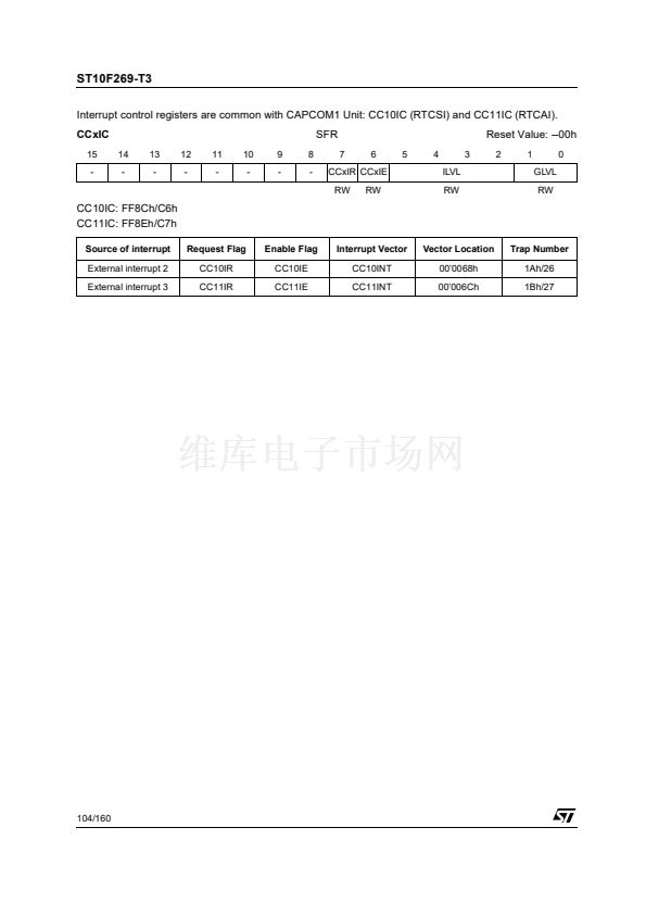
As all other capture inputs, the capture input
function of pins P2.15...P2.0 can also be used as
external interrupt inputs (250ns sample rate at
32MHz CPU clock).
The upper eight Port 2 lines (P2.15...P2.8) also
can serve as Fast External Interrupt inputs from
EX0IN to EX7IN (Fast external interrupt sampling
rate is 31.25ns at 32MHz CPU clock).
P2.15 in addition serves as input for CAPCOM2
timer T7 (T7IN). The Table 15 summarizes the
alternate functions of Port 2.
Fast External Interrupt 0 Input
Fast External Interrupt 1 Input
Fast External Interrupt 2 Input
Fast External Interrupt 3 Input
Fast External Interrupt 4 Input
Fast External Interrupt 5 Input
Fast External Interrupt 6 Input
Fast External Interrupt 7 Input
Figure 25 :
Port 2 I/O and Alternate Functions
Alternate Function
P2.15
P2.14
P2.13
P2.12
P2.11
P2.10
P2.9
P2.8
P2.7
P2.6
P2.5
P2.4
P2.3
P2.2
P2.1
P2.0
a)
CC15IO
CC14IO
CC13IO
CC12IO
CC11IO
CC10IO
CC9IO
CC8IO
CC7IO
CC6IO
CC5IO
CC4IO
CC3IO
CC2IO
CC1IO
CC0IO
CAPCOM1
Capture Input / Compare Output
b)
EX7IN
EX6IN
EX5IN
EX4IN
EX3IN
EX2IN
EX1IN
EX0IN
c)
T7IN
Port 2
General Purpose
Input / Output
Fast External
Interrupt Input
CAPCOM2
Timer T7 Input
67/160


 1
1
 2
2
 3
3
 4
4
 5
5
 6
6
 7
7
 8
8
 9
9
 10
10
 11
11
 12
12
 13
13
 14
14
 15
15
 16
16
 17
17
 18
18
 19
19
 20
20
 21
21
 22
22
 23
23
 24
24
 25
25
 26
26
 27
27
 28
28
 29
29
 30
30
 31
31
 32
32
 33
33
 34
34
 35
35
 36
36
 37
37
 38
38
 39
39
 40
40
 41
41
 42
42
 43
43
 44
44
 45
45
 46
46
 47
47
 48
48
 49
49
 50
50
 51
51
 52
52
 53
53
 54
54
 55
55
 56
56
 57
57
 58
58
 59
59
 60
60
 61
61
 62
62
 63
63
 64
64
 65
65
 66
66
 67
67
 68
68
 69
69
 70
70
 71
71
 72
72
 73
73
 74
74
 75
75
 76
76
 77
77
 78
78
 79
79
 80
80
 81
81
 82
82
 83
83
 84
84
 85
85
 86
86
 87
87
 88
88
 89
89
 90
90
 91
91
 92
92
 93
93
 94
94
 95
95
 96
96
 97
97
 98
98
 99
99
 100
100
 101
101
 102
102
 103
103
 104
104
 105
105
 106
106
 107
107
 108
108
 109
109
 110
110
 111
111
 112
112
 113
113
 114
114
 115
115
 116
116
 117
117
 118
118
 119
119
 120
120
 121
121
 122
122
 123
123
 124
124
 125
125
 126
126
 127
127
 128
128
 129
129
 130
130
 131
131
 132
132
 133
133
 134
134
 135
135
 136
136
 137
137
 138
138
 139
139
 140
140
 141
141
 142
142
 143
143
 144
144
 145
145
 146
146
 147
147
 148
148
 149
149
 150
150
 151
151
 152
152
 153
153
 154
154
 155
155
 156
156
 157
157
 158
158
 159
159
 160
160
