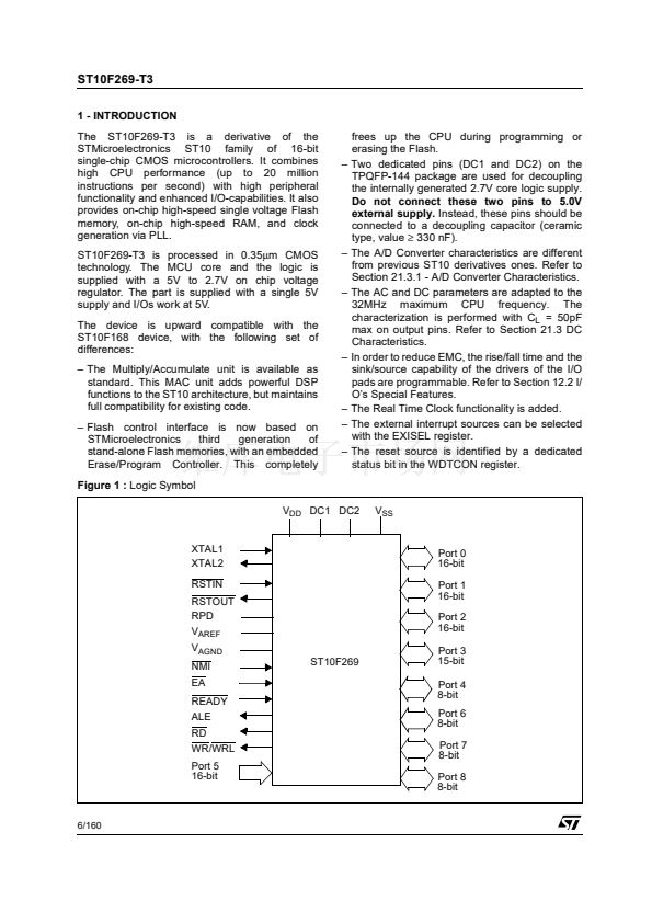
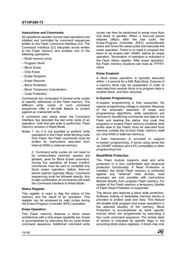
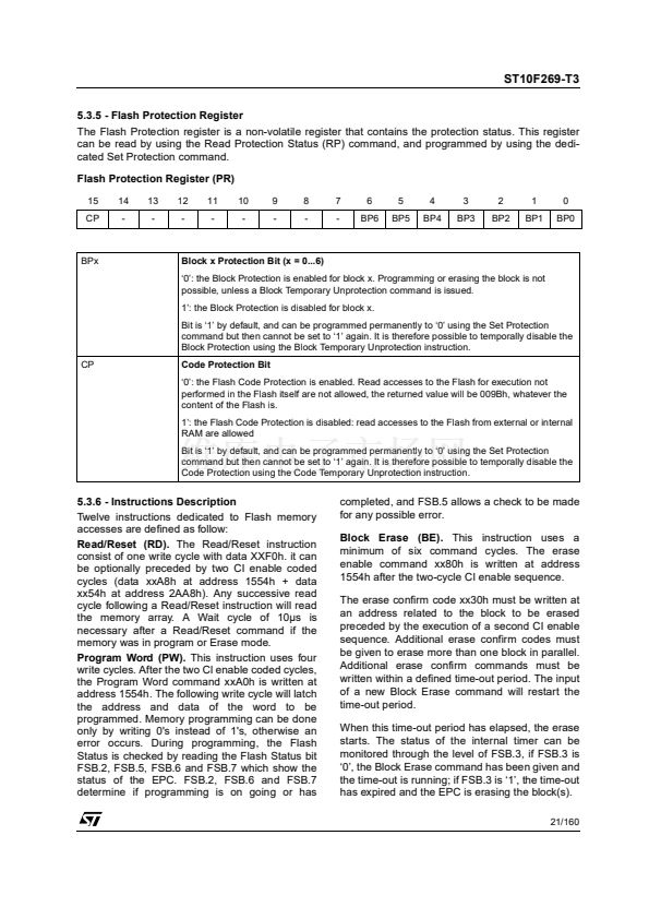
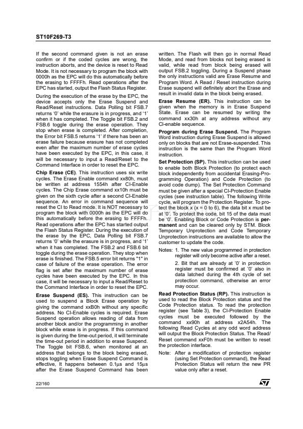
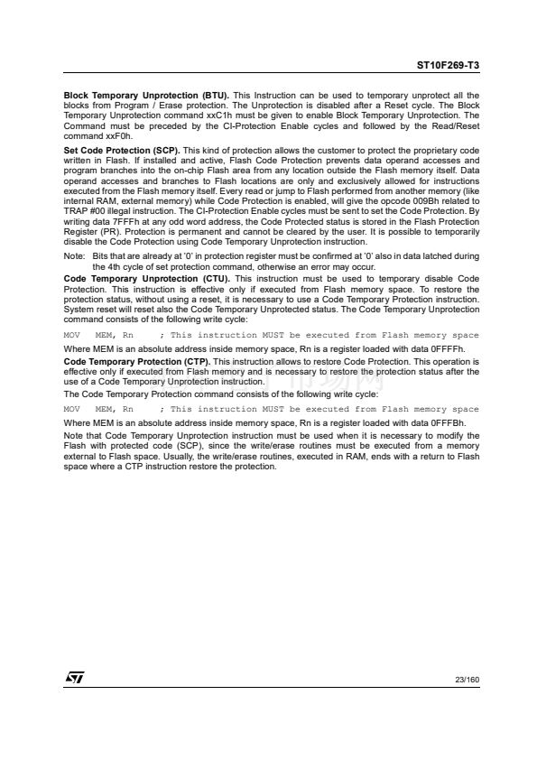
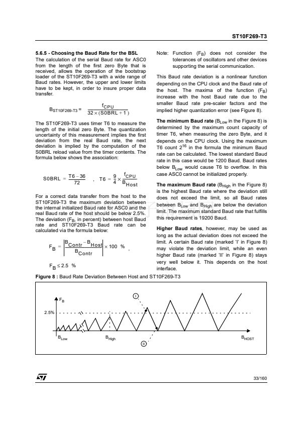
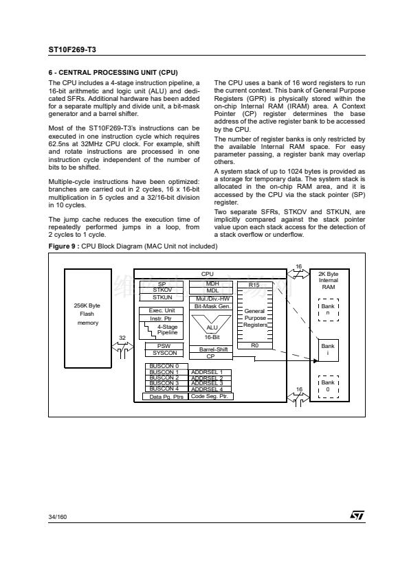
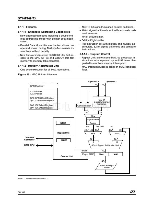
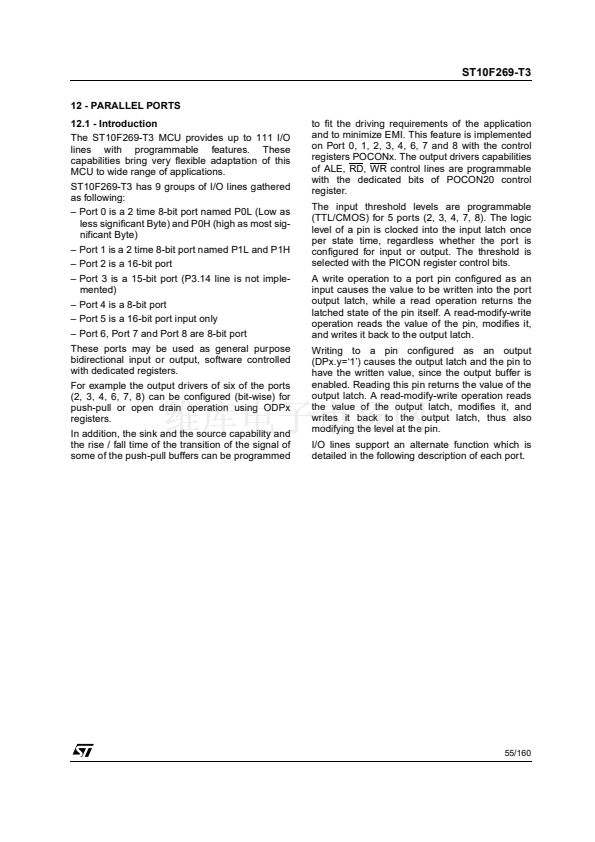
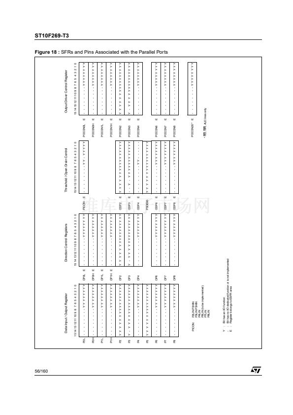
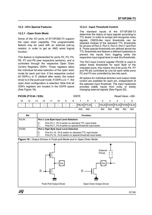
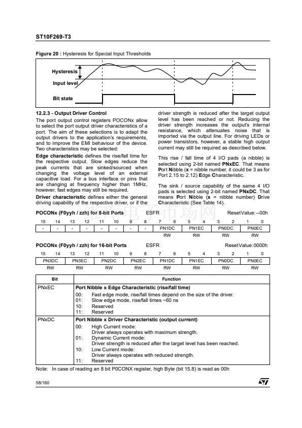
ST10F269-T3
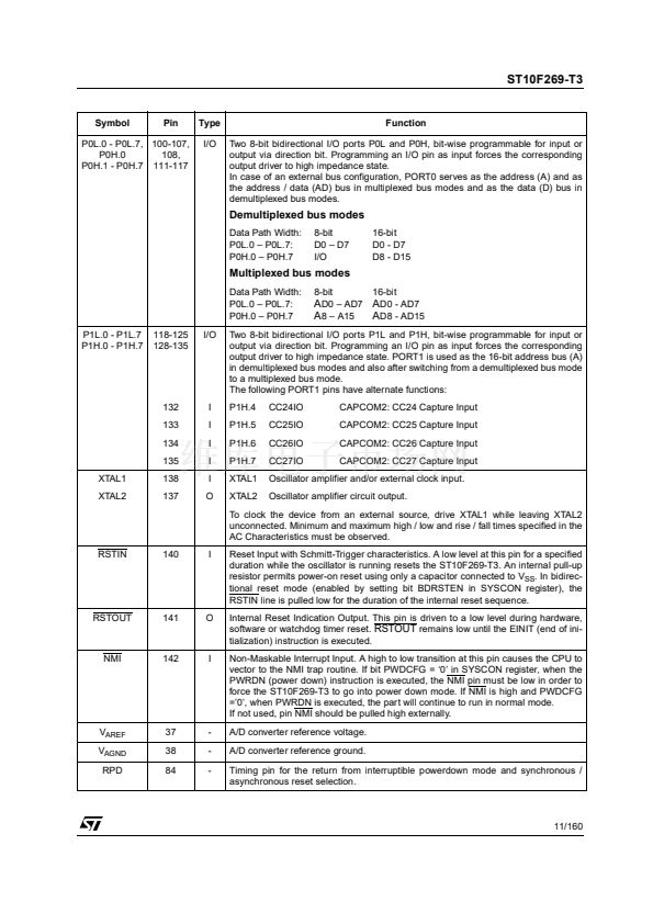
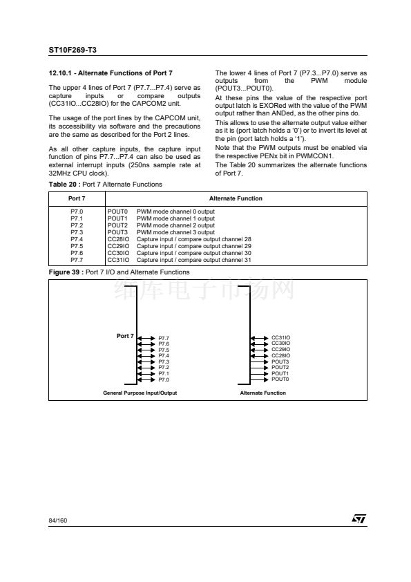
12.10.1 - Alternate Functions of Port 7
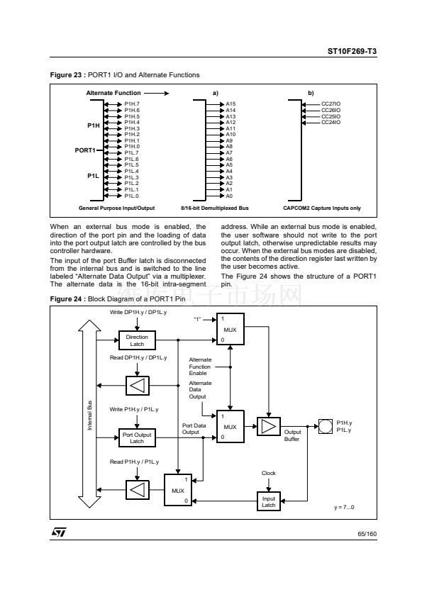
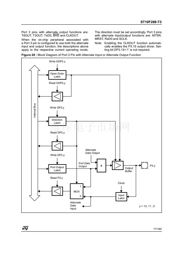
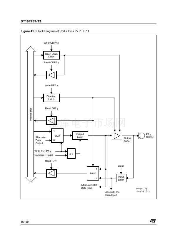
The upper 4 lines of Port 7 (P7.7...P7.4) serve as
capture
inputs
or
compare
outputs
(CC31IO...CC28IO) for the CAPCOM2 unit.
The usage of the port lines by the CAPCOM unit,
its accessibility via software and the precautions
are the same as described for the Port 2 lines.
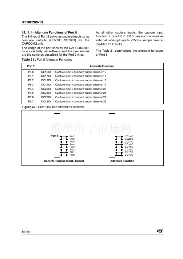
As all other capture inputs, the capture input
function of pins P7.7...P7.4 can also be used as
external interrupt inputs (250ns sample rate at
32MHz CPU clock).
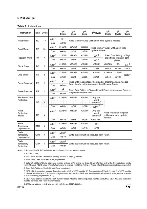
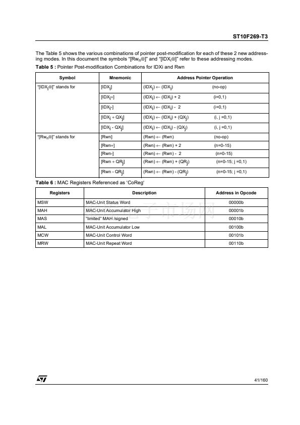
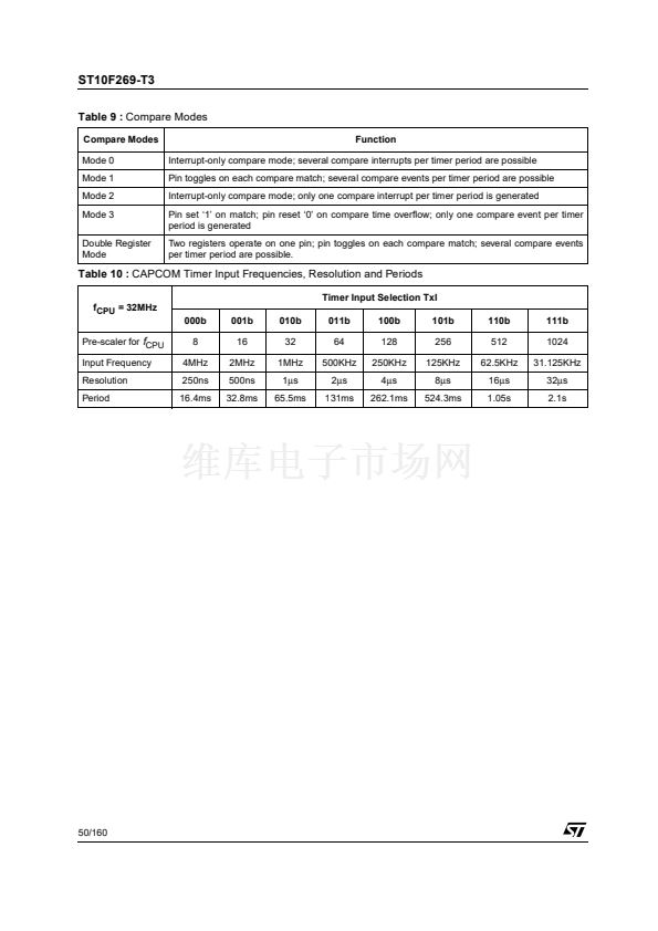
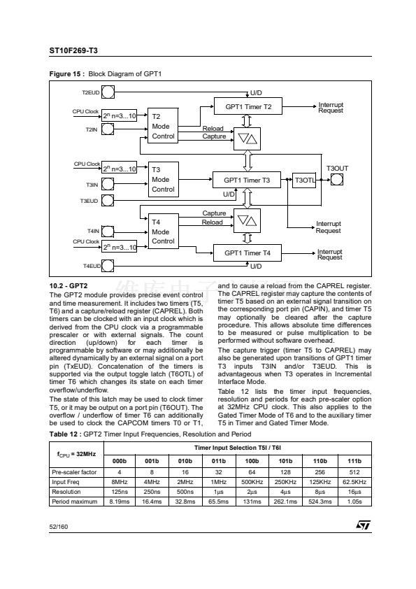
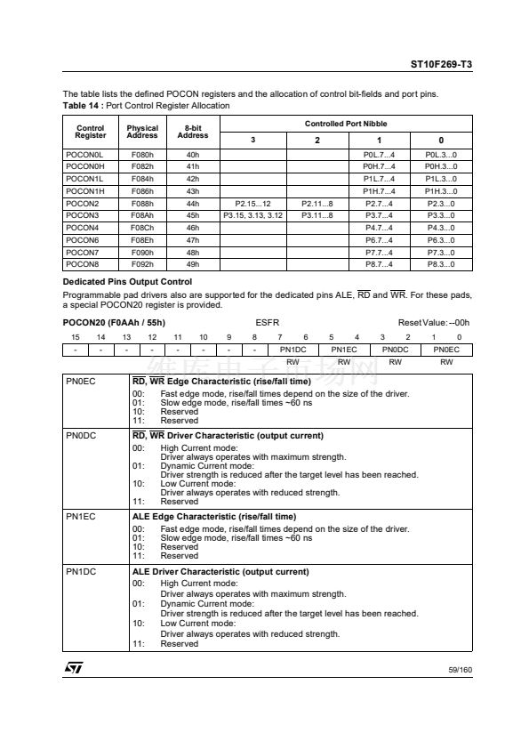
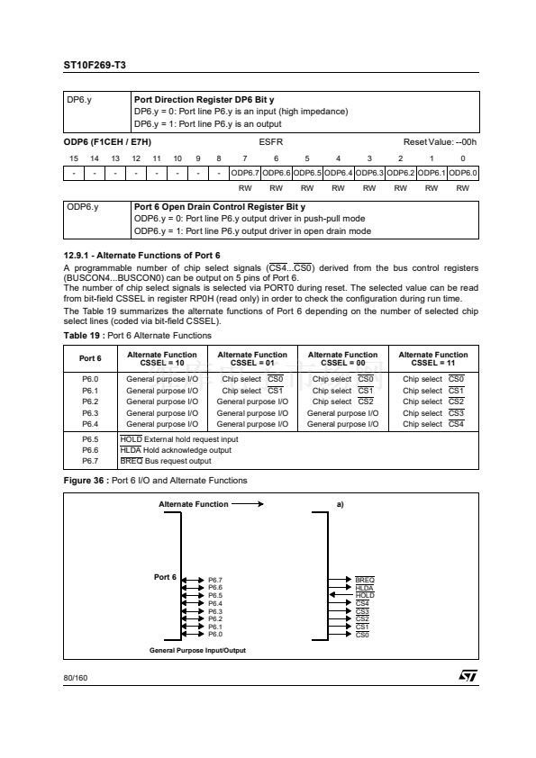
Table 20 :
Port 7 Alternate Functions
Port 7
P7.0
P7.1
P7.2
P7.3
P7.4
P7.5
P7.6
P7.7
POUT0
POUT1
POUT2
POUT3
CC28IO
CC29IO
CC30IO
CC31IO
Alternate Function
PWM mode channel 0 output
PWM mode channel 1 output
PWM mode channel 2 output
PWM mode channel 3 output
Capture input / compare output channel 28
Capture input / compare output channel 29
Capture input / compare output channel 30
Capture input / compare output channel 31
The lower 4 lines of Port 7 (P7.3...P7.0) serve as
outputs
from
the
PWM
module
(POUT3...POUT0).
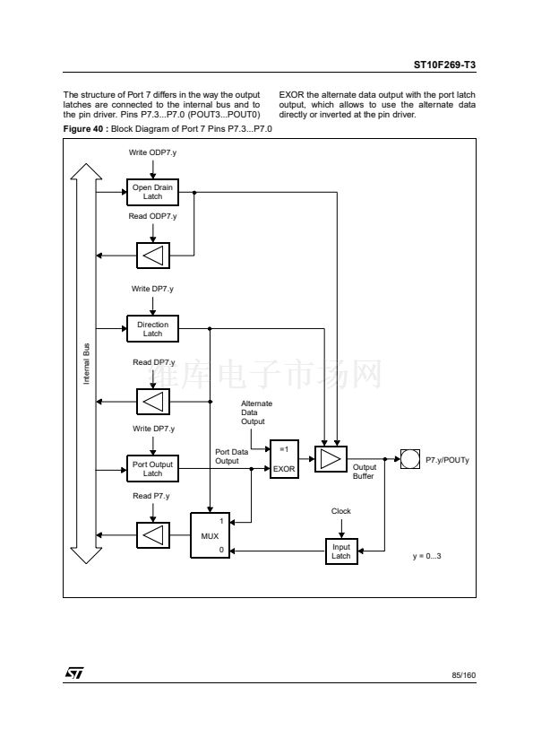
At these pins the value of the respective port
output latch is EXORed with the value of the PWM
output rather than ANDed, as the other pins do.
This allows to use the alternate output value either
as it is (port latch holds a 鈥?鈥? or to invert its level at
the pin (port latch holds a 鈥?鈥?.
Note that the PWM outputs must be enabled via
the respective PENx bit in PWMCON1.
The Table 20 summarizes the alternate functions
of Port 7.
Figure 39 :
Port 7 I/O and Alternate Functions
Port 7
P7.7
P7.6
P7.5
P7.4
P7.3
P7.2
P7.1
P7.0
CC31IO
CC30IO
CC29IO
CC28IO
POUT3
POUT2
POUT1
POUT0
Alternate Function
General Purpose Input/Output
84/160


 1
1
 2
2
 3
3
 4
4
 5
5
 6
6
 7
7
 8
8
 9
9
 10
10
 11
11
 12
12
 13
13
 14
14
 15
15
 16
16
 17
17
 18
18
 19
19
 20
20
 21
21
 22
22
 23
23
 24
24
 25
25
 26
26
 27
27
 28
28
 29
29
 30
30
 31
31
 32
32
 33
33
 34
34
 35
35
 36
36
 37
37
 38
38
 39
39
 40
40
 41
41
 42
42
 43
43
 44
44
 45
45
 46
46
 47
47
 48
48
 49
49
 50
50
 51
51
 52
52
 53
53
 54
54
 55
55
 56
56
 57
57
 58
58
 59
59
 60
60
 61
61
 62
62
 63
63
 64
64
 65
65
 66
66
 67
67
 68
68
 69
69
 70
70
 71
71
 72
72
 73
73
 74
74
 75
75
 76
76
 77
77
 78
78
 79
79
 80
80
 81
81
 82
82
 83
83
 84
84
 85
85
 86
86
 87
87
 88
88
 89
89
 90
90
 91
91
 92
92
 93
93
 94
94
 95
95
 96
96
 97
97
 98
98
 99
99
 100
100
 101
101
 102
102
 103
103
 104
104
 105
105
 106
106
 107
107
 108
108
 109
109
 110
110
 111
111
 112
112
 113
113
 114
114
 115
115
 116
116
 117
117
 118
118
 119
119
 120
120
 121
121
 122
122
 123
123
 124
124
 125
125
 126
126
 127
127
 128
128
 129
129
 130
130
 131
131
 132
132
 133
133
 134
134
 135
135
 136
136
 137
137
 138
138
 139
139
 140
140
 141
141
 142
142
 143
143
 144
144
 145
145
 146
146
 147
147
 148
148
 149
149
 150
150
 151
151
 152
152
 153
153
 154
154
 155
155
 156
156
 157
157
 158
158
 159
159
 160
160
