Philips Semiconductors
SC16C654B/654DB
5 V, 3.3 V and 2.5 V quad UART, 5 Mbit/s (max.) with 64-byte FIFOs
Holding Register (RHR) has not been read following the loading of a character or the
receive trigger level has not been reached. (For a description of this timing, see
Section
6.4 鈥淗ardware 铿俹w control鈥?)
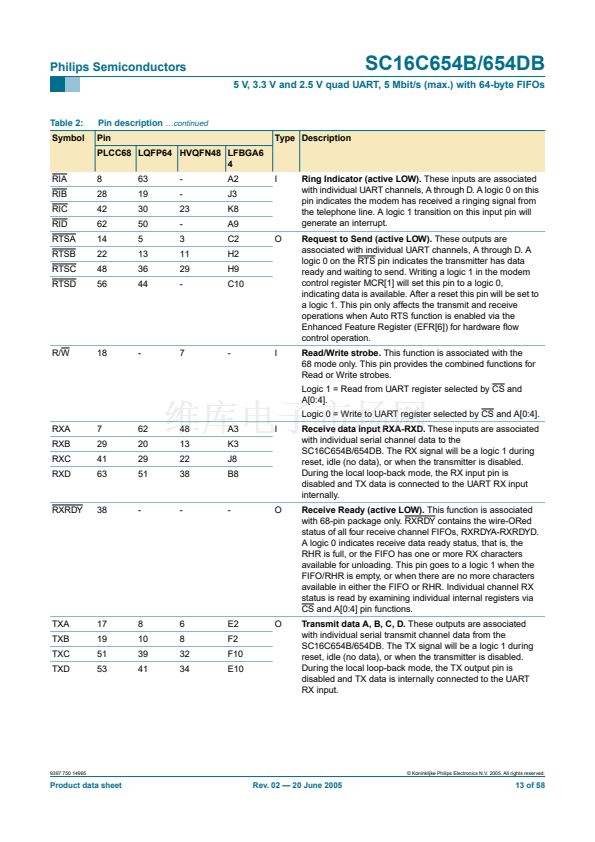
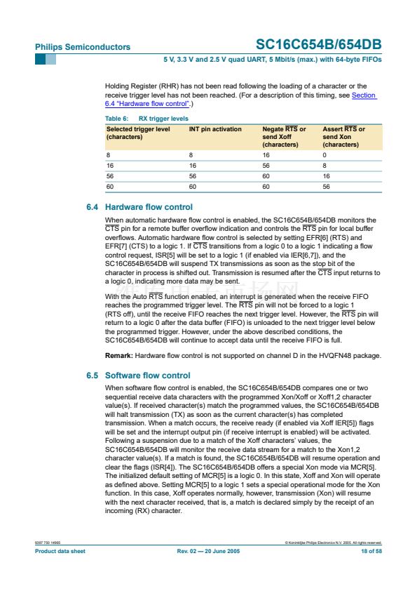
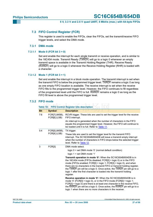
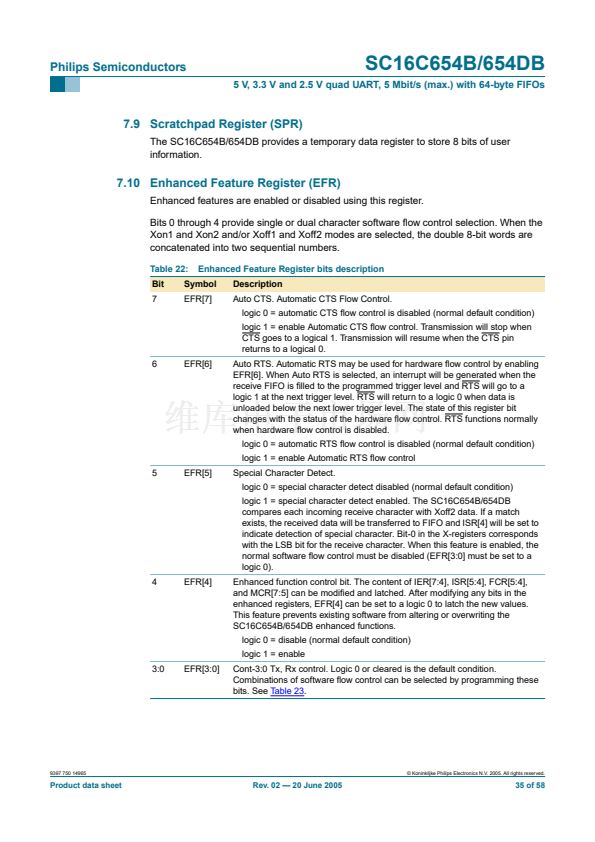
Table 6:
RX trigger levels
INT pin activation
Negate RTS or
send Xoff
(characters)
16
56
60
60
Assert RTS or
send Xon
(characters)
0
8
16
56
Selected trigger level
(characters)
8
16
56
60
8
16
56
60
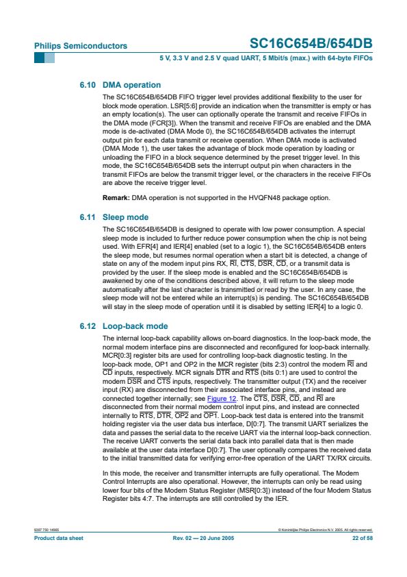
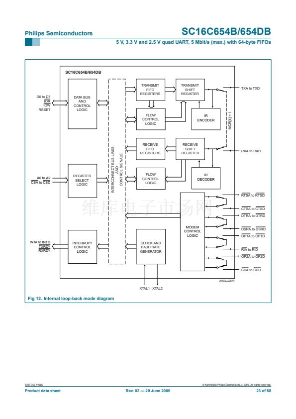
6.4 Hardware 铿俹w control
When automatic hardware 铿俹w control is enabled, the SC16C654B/654DB monitors the
CTS pin for a remote buffer over铿俹w indication and controls the RTS pin for local buffer
over铿俹ws. Automatic hardware 铿俹w control is selected by setting EFR[6] (RTS) and
EFR[7] (CTS) to a logic 1. If CTS transitions from a logic 0 to a logic 1 indicating a 铿俹w
control request, ISR[5] will be set to a logic 1 (if enabled via IER[6,7]), and the
SC16C654B/654DB will suspend TX transmissions as soon as the stop bit of the
character in process is shifted out. Transmission is resumed after the CTS input returns to
a logic 0, indicating more data may be sent.
With the Auto RTS function enabled, an interrupt is generated when the receive FIFO
reaches the programmed trigger level. The RTS pin will not be forced to a logic 1
(RTS off), until the receive FIFO reaches the next trigger level. However, the RTS pin will
return to a logic 0 after the data buffer (FIFO) is unloaded to the next trigger level below
the programmed trigger. However, under the above described conditions, the
SC16C654B/654DB will continue to accept data until the receive FIFO is full.
Remark:
Hardware 铿俹w control is not supported on channel D in the HVQFN48 package.
6.5 Software 铿俹w control
When software 铿俹w control is enabled, the SC16C654B/654DB compares one or two
sequential receive data characters with the programmed Xon/Xoff or Xoff1,2 character
value(s). If received character(s) match the programmed values, the SC16C654B/654DB
will halt transmission (TX) as soon as the current character(s) has completed
transmission. When a match occurs, the receive ready (if enabled via Xoff IER[5]) 铿俛gs
will be set and the interrupt output pin (if receive interrupt is enabled) will be activated.
Following a suspension due to a match of the Xoff characters鈥?values, the
SC16C654B/654DB will monitor the receive data stream for a match to the Xon1,2
character value(s). If a match is found, the SC16C654B/654DB will resume operation and
clear the 铿俛gs (ISR[4]). The SC16C654B/654DB offers a special Xon mode via MCR[5].
The initialized default setting of MCR[5] is a logic 0. In this state, Xoff and Xon will operate
as de铿乶ed above. Setting MCR[5] to a logic 1 sets a special operational mode for the Xon
function. In this case, Xoff operates normally, however, transmission (Xon) will resume
with the next character received, that is, a match is declared simply by the receipt of an
incoming (RX) character.
9397 750 14965
漏 Koninklijke Philips Electronics N.V. 2005. All rights reserved.
Product data sheet
Rev. 02 鈥?20 June 2005
18 of 58


 1
1
 2
2
 3
3
 4
4
 5
5
 6
6
 7
7
 8
8
 9
9
 10
10
 11
11
 12
12
 13
13
 14
14
 15
15
 16
16
 17
17
 18
18
 19
19
 20
20
 21
21
 22
22
 23
23
 24
24
 25
25
 26
26
 27
27
 28
28
 29
29
 30
30
 31
31
 32
32
 33
33
 34
34
 35
35
 36
36
 37
37
 38
38
 39
39
 40
40
 41
41
 42
42
 43
43
 44
44
 45
45
 46
46
 47
47
 48
48
 49
49
 50
50
 51
51
 52
52
 53
53
 54
54
 55
55
 56
56
 57
57
 58
58
