Philips Semiconductors
SC16C654B/654DB
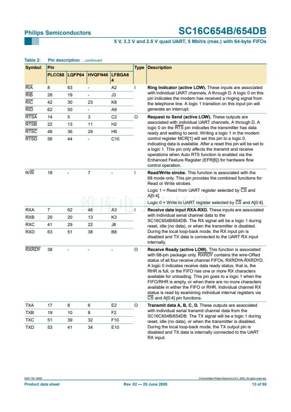
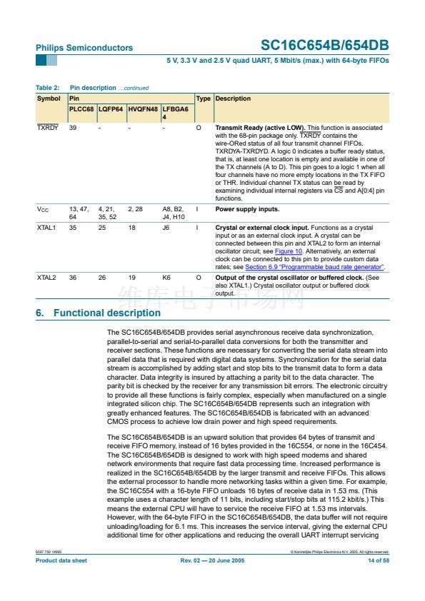
5 V, 3.3 V and 2.5 V quad UART, 5 Mbit/s (max.) with 64-byte FIFOs
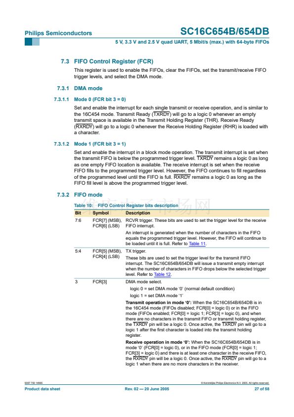
7.9 Scratchpad Register (SPR)
The SC16C654B/654DB provides a temporary data register to store 8 bits of user
information.
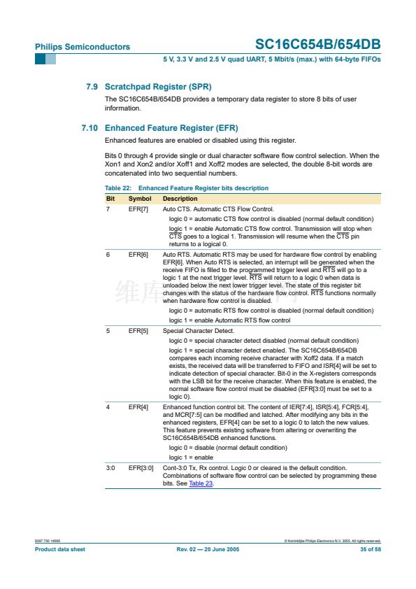
7.10 Enhanced Feature Register (EFR)
Enhanced features are enabled or disabled using this register.
Bits 0 through 4 provide single or dual character software 铿俹w control selection. When the
Xon1 and Xon2 and/or Xoff1 and Xoff2 modes are selected, the double 8-bit words are
concatenated into two sequential numbers.
Table 22:
Bit
7
Enhanced Feature Register bits description
Description
Auto CTS. Automatic CTS Flow Control.
logic 0 = automatic CTS 铿俹w control is disabled (normal default condition)
logic 1 = enable Automatic CTS 铿俹w control. Transmission will stop when
CTS goes to a logical 1. Transmission will resume when the CTS pin
returns to a logical 0.
6
EFR[6]
Auto RTS. Automatic RTS may be used for hardware 铿俹w control by enabling
EFR[6]. When Auto RTS is selected, an interrupt will be generated when the
receive FIFO is 铿乴led to the programmed trigger level and RTS will go to a
logic 1 at the next trigger level. RTS will return to a logic 0 when data is
unloaded below the next lower trigger level. The state of this register bit
changes with the status of the hardware 铿俹w control. RTS functions normally
when hardware 铿俹w control is disabled.
logic 0 = automatic RTS 铿俹w control is disabled (normal default condition)
logic 1 = enable Automatic RTS 铿俹w control
5
EFR[5]
Special Character Detect.
logic 0 = special character detect disabled (normal default condition)
logic 1 = special character detect enabled. The SC16C654B/654DB
compares each incoming receive character with Xoff2 data. If a match
exists, the received data will be transferred to FIFO and ISR[4] will be set to
indicate detection of special character. Bit-0 in the X-registers corresponds
with the LSB bit for the receive character. When this feature is enabled, the
normal software 铿俹w control must be disabled (EFR[3:0] must be set to a
logic 0).
4
EFR[4]
Enhanced function control bit. The content of IER[7:4], ISR[5:4], FCR[5:4],
and MCR[7:5] can be modi铿乪d and latched. After modifying any bits in the
enhanced registers, EFR[4] can be set to a logic 0 to latch the new values.
This feature prevents existing software from altering or overwriting the
SC16C654B/654DB enhanced functions.
logic 0 = disable (normal default condition)
logic 1 = enable
3:0
EFR[3:0]
Cont-3:0 Tx, Rx control. Logic 0 or cleared is the default condition.
Combinations of software 铿俹w control can be selected by programming these
bits. See
Table 23.
Symbol
EFR[7]
9397 750 14965
漏 Koninklijke Philips Electronics N.V. 2005. All rights reserved.
Product data sheet
Rev. 02 鈥?20 June 2005
35 of 58


 1
1
 2
2
 3
3
 4
4
 5
5
 6
6
 7
7
 8
8
 9
9
 10
10
 11
11
 12
12
 13
13
 14
14
 15
15
 16
16
 17
17
 18
18
 19
19
 20
20
 21
21
 22
22
 23
23
 24
24
 25
25
 26
26
 27
27
 28
28
 29
29
 30
30
 31
31
 32
32
 33
33
 34
34
 35
35
 36
36
 37
37
 38
38
 39
39
 40
40
 41
41
 42
42
 43
43
 44
44
 45
45
 46
46
 47
47
 48
48
 49
49
 50
50
 51
51
 52
52
 53
53
 54
54
 55
55
 56
56
 57
57
 58
58
