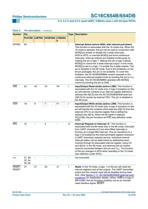
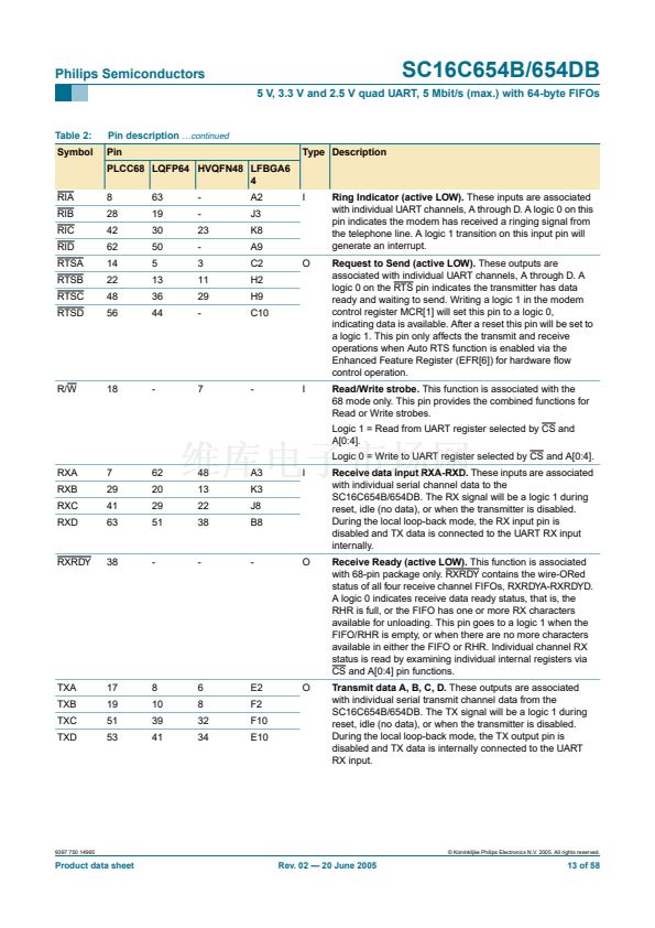
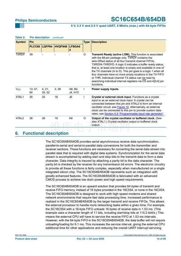
Philips Semiconductors
SC16C654B/654DB
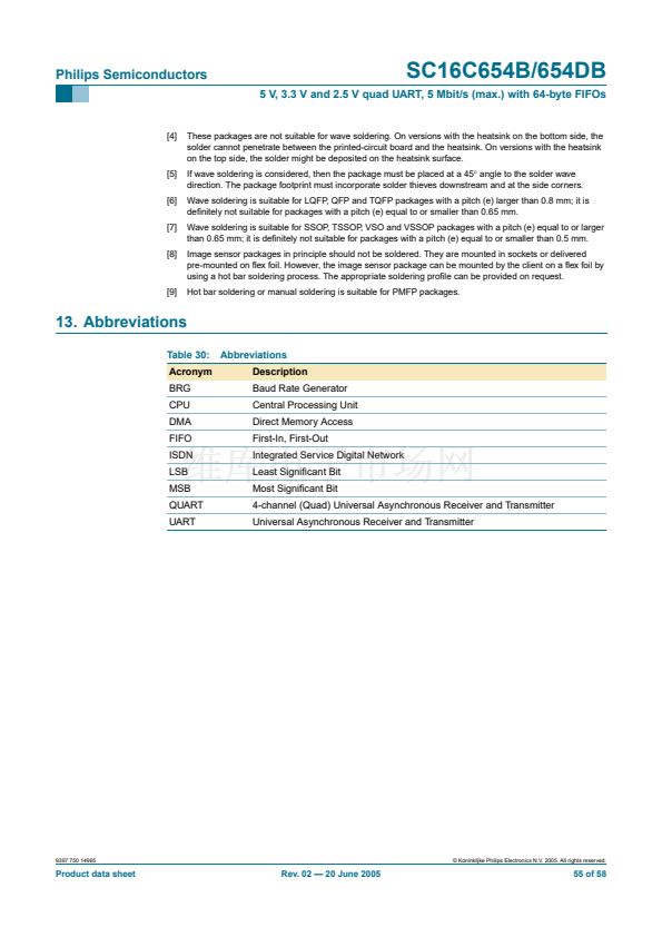
5 V, 3.3 V and 2.5 V quad UART, 5 Mbit/s (max.) with 64-byte FIFOs
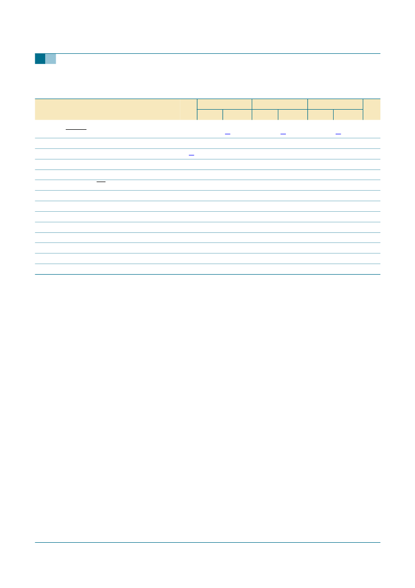
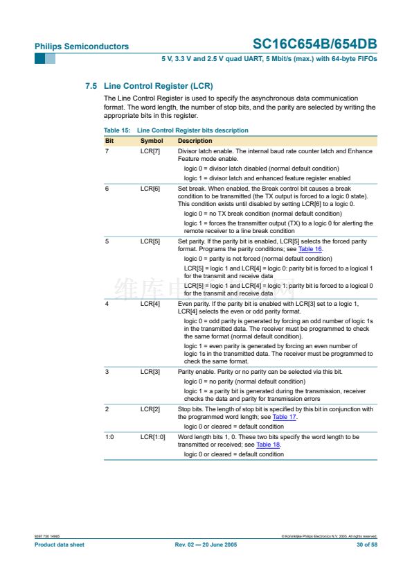
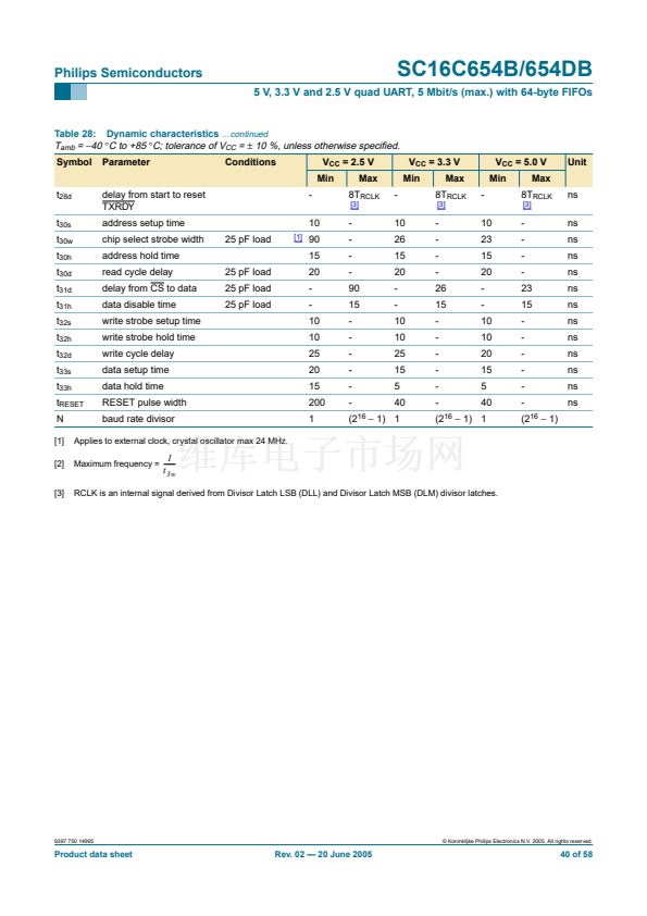
Table 28: Dynamic characteristics
鈥ontinued
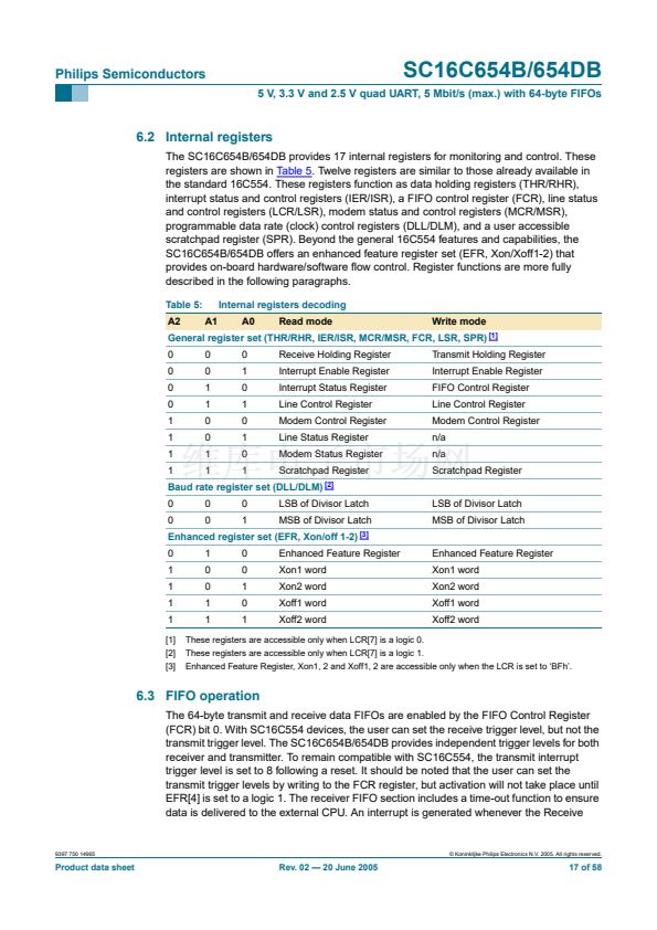
T
amb
=
鈭?/div>
40
掳
C to +85
掳
C; tolerance of V
CC
=
卤
10 %, unless otherwise speci铿乪d.
Symbol
t
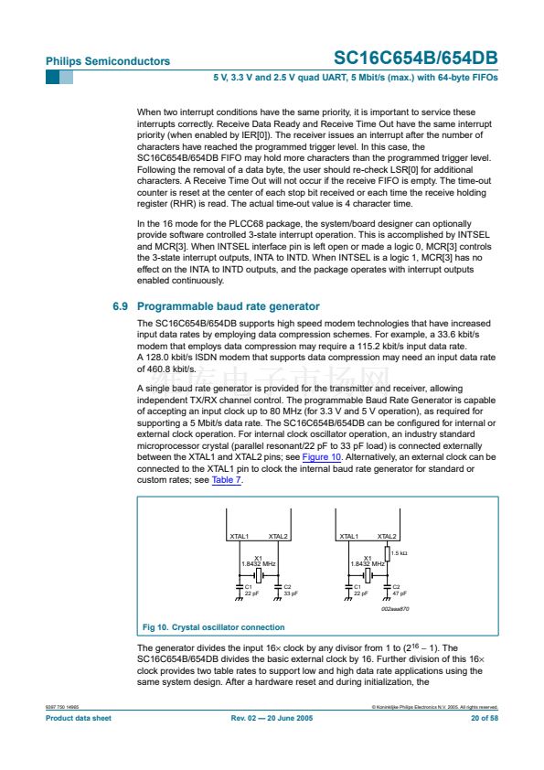
28d
t
30s
t
30w
t
30h
t
30d
t
31d
t
31h
t
32s
t
32h
t
32d
t
33s
t
33h
t
RESET
N
[1]
[2]
[3]
Parameter
delay from start to reset
TXRDY
address setup time
chip select strobe width
address hold time
read cycle delay
delay from CS to data
data disable time
write strobe setup time
write strobe hold time
write cycle delay
data setup time
data hold time
RESET pulse width
baud rate divisor
Conditions
-
10
25 pF load
25 pF load
25 pF load
25 pF load
[1]
V
CC
= 2.5 V
Min
[3]
V
CC
= 3.3 V
Min
-
10
26
15
20
-
-
10
10
25
15
5
40
[3]
V
CC
= 5.0 V
Min
-
10
23
15
20
-
-
10
10
20
15
5
40
[3]
Unit
ns
ns
ns
ns
ns
ns
ns
ns
ns
ns
ns
ns
ns
Max
8T
RCLK
-
-
-
-
90
15
-
-
-
-
-
-
Max
8T
RCLK
-
-
-
-
26
15
-
-
-
-
-
-
Max
8T
RCLK
-
-
-
-
23
15
-
-
-
-
-
-
(2
16
鈭?/div>
1)
90
15
20
-
-
10
10
25
20
15
200
1
(2
16
鈭?/div>
1) 1
(2
16
鈭?/div>
1) 1
Applies to external clock, crystal oscillator max 24 MHz.
Maximum frequency =
-------
RCLK is an internal signal derived from Divisor Latch LSB (DLL) and Divisor Latch MSB (DLM) divisor latches.
1
t
3w
9397 750 14965
漏 Koninklijke Philips Electronics N.V. 2005. All rights reserved.
Product data sheet
Rev. 02 鈥?20 June 2005
40 of 58


 1
1
 2
2
 3
3
 4
4
 5
5
 6
6
 7
7
 8
8
 9
9
 10
10
 11
11
 12
12
 13
13
 14
14
 15
15
 16
16
 17
17
 18
18
 19
19
 20
20
 21
21
 22
22
 23
23
 24
24
 25
25
 26
26
 27
27
 28
28
 29
29
 30
30
 31
31
 32
32
 33
33
 34
34
 35
35
 36
36
 37
37
 38
38
 39
39
 40
40
 41
41
 42
42
 43
43
 44
44
 45
45
 46
46
 47
47
 48
48
 49
49
 50
50
 51
51
 52
52
 53
53
 54
54
 55
55
 56
56
 57
57
 58
58
