1.6 second timeout period or for an adjustable timeout period.
ADM691/ADM693/ADM695 automatically selects the 鈥渓ong鈥?/div>
timeout period directly after a reset is issued. The watchdog
timer is restarted at the end of reset, whether the reset was
caused by lack of activity on WDI or by V
CC
falling below the
reset threshold.
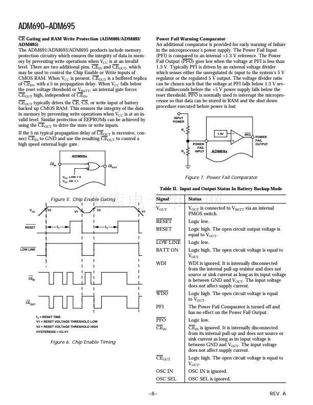
The normal (short) timeout period becomes effective following
the first transition of WDI after
RESET
has gone inactive. The
watchdog timeout period restarts with each transition on the
WDI pin. To ensure that the watchdog timer does not time out,
either a high-to-low or low-to-high transition on the WDI pin
must occur at or less than the minimum timeout period. If WDI
remains permanently either high or low, reset pulses will be
issued after each 鈥渓ong鈥?timeout period (1.6 s). The watchdog
monitor can be deactivated by floating the Watchdog Input
(WDI) or by connecting it to midsupply.
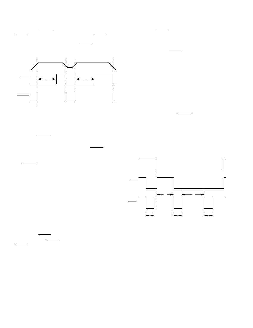
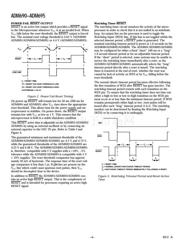
t
1
= RESET TIME.
V1 = RESET VOLTAGE THRESHOLD LOW
V2 = RESET VOLTAGE THRESHOLD HIGH
HYSTERESIS = V2鈥揤1
Figure 2. Power Fail Reset Timing
On power-up
RESET
will remain low for 50 ms (200 ms for
ADM694 and ADM695) after V
CC
rises above the appropriate
reset threshold. This allows time for the power supply and mi-
croprocessor to stabilize. On power-down, the
RESET
output
remains low with V
CC
as low as 1 V. This ensures that the
microprocessor is held in a stable shutdown condition.
This
RESET
active time is adjustable on the ADM691/ADM693/
ADM695 by using an external oscillator or by connecting an
external capacitor to the OSC IN pin. Refer to Table I and
Figure 4.
The guaranteed minimum and maximum thresholds of the
ADM690/ADM691/ADM694/ADM695 are 4.5 V and 4.73 V,
while the guaranteed thresholds of the ADM692/ADM693 are
4.25 V and 4.48 V. The ADM690/ADM691/ADM694/ADM695
is, therefore, compatible with 5 V supplies with a +10%, 鈥?%
tolerance while the ADM692/ADM693 is compatible with 5 V
卤
10% supplies. The reset threshold comparator has approxi-
mately 50 mV of hysteresis. The response time of the reset volt-
age comparator is less than 1
碌s.
If glitches are present on the
V
CC
line which could cause spurious reset pulses, then V
CC
should be decoupled close to the device.
In addition to
RESET
the ADM691/ADM693/ADM695 con-
tain an active high
RESET
output. This is the complement of
RESET
and is intended for processors requiring an active high
RESET signal.
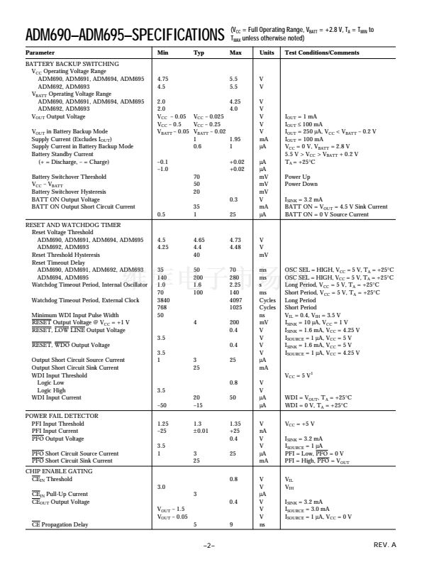
WDI
WDO
t
2
RESET
t
3
t
1
t
1
t
1
t
1
= RESET TIME.
t
2
= NORMAL (SHORT) WATCHDOG TIMEOUT PERIOD.
t
3
= WATCHDOG TIMEOUT PERIOD IMMEDIATELY FOLLOWING A RESET.
Figure 3. Watchdog Timeout Period and Reset Active
Time
prev
next


 1
1
 2
2
 3
3
 4
4
 5
5
 6
6
 7
7
 8
8
 9
9
 10
10
 11
11
 12
12
 13
13
 14
14
 15
15
 16
16
