CY7C64713
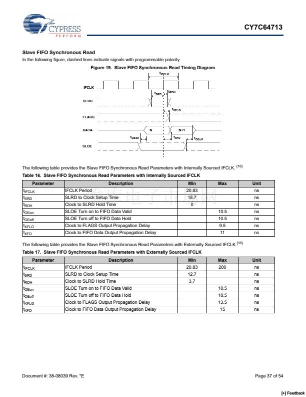
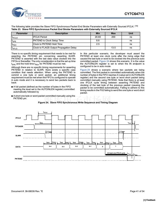
Slave FIFO Synchronous Address
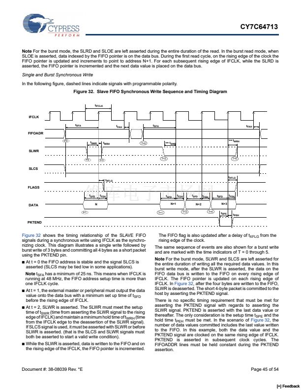
Figure 28. Slave FIFO Synchronous Address Timing Diagram
IFCLK
SLCS/FIFOADR [1:0]
t
SFA
t
FAH
The following table provides the Slave FIFO Synchronous Address Parameters.
[16]
Table 27. Slave FIFO Synchronous Address Parameters
Parameter
t
IFCLK
t
SFA
t
FAH
Description
Interface Clock Period
FIFOADR[1:0] to Clock Setup Time
Clock to FIFOADR[1:0] Hold Time
Min
20.83
25
10
Max
200
Unit
ns
ns
ns
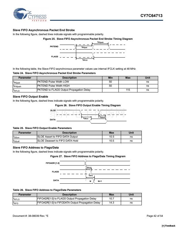
Slave FIFO Asynchronous Address
In the following figure, dashed lines indicate signals with programmable polarity.
Figure 29. Slave FIFO Asynchronous Address Timing Diagram
SLCS/FIFOADR [1:0]
t
SFA
RD/WR/PKTEND
t
FAH
In the following table, the Slave FIFO asynchronous parameter values use internal IFCLK setting at 48 MHz
.
Table 28. Slave FIFO Asynchronous Address Parameters
Parameter
t
SFA
t
FAH
Description
FIFOADR[1:0] to RD/WR/PKTEND Setup Time
RD/WR/PKTEND to FIFOADR[1:0] Hold Time
Min
10
10
Unit
ns
ns
Document #: 38-08039 Rev. *E
Page 43 of 54
[+] Feedback


 1
1
 2
2
 3
3
 4
4
 5
5
 6
6
 7
7
 8
8
 9
9
 10
10
 11
11
 12
12
 13
13
 14
14
 15
15
 16
16
 17
17
 18
18
 19
19
 20
20
 21
21
 22
22
 23
23
 24
24
 25
25
 26
26
 27
27
 28
28
 29
29
 30
30
 31
31
 32
32
 33
33
 34
34
 35
35
 36
36
 37
37
 38
38
 39
39
 40
40
 41
41
 42
42
 43
43
 44
44
 45
45
 46
46
 47
47
 48
48
 49
49
 50
50
 51
51
 52
52
 53
53
 54
54
