DS1802
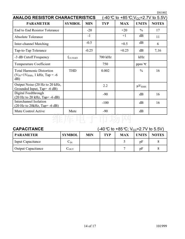
7. Tap-to-tap tolerance is used to determine the change in voltage between successive tap positions. The
DS1802 is specified for
卤0.25
dB tap-to-tap tolerance.
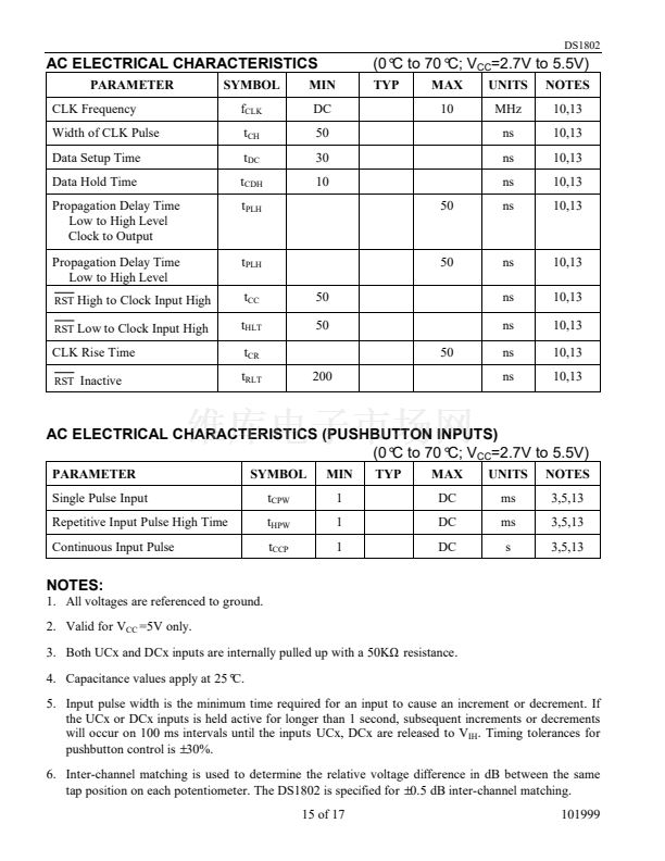
8. Typical values are for t
A
=25掳 and nominal supply voltage.
C
9. Power-up time is the time for all pushbutton inputs to be stable and active once power has reached a
valid level, 2.7V min.
10. See Figure 6.
11. Absolute tolerance is used to determine measured wiper voltage vs. expected wiper voltage as
determined by wiper position. The DS1802 is bounded by a
卤1
dB absolute tolerance.
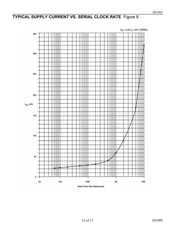
12. Maximum current specifications are based on clock rate, active zero-crossing detection, and
pushbutton activation. See Figure 8 for clock rate vs. current specification.
13. Valid for V
CC
=3V or 5V.
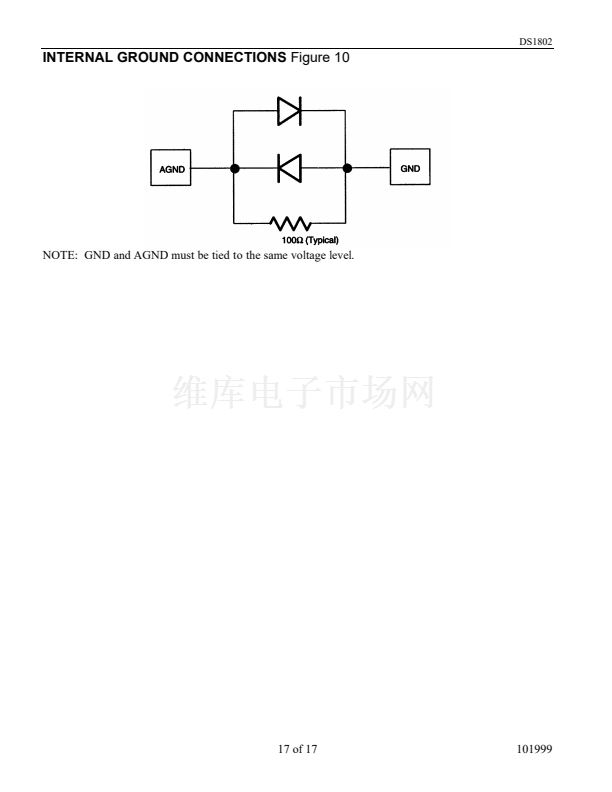
14. See Figure 10.
15. Standby current levels apply when all inputs are driven to appropriate supply levels.
16. These parameters are characterized and not 100% tested.
17. Valid at 25掳 only.
C
DIGITAL OUTPUT LOAD
Figure 9
16 of 17
101999


 1
1
 2
2
 3
3
 4
4
 5
5
 6
6
 7
7
 8
8
 9
9
 10
10
 11
11
 12
12
 13
13
 14
14
 15
15
 16
16
 17
17
