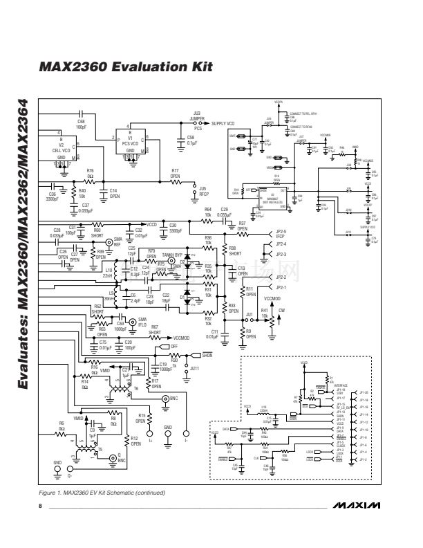
tank with an external LO source. The VCO_BYP bit
should be set to 1 to enable this port. Stuff C24 and
C25 with AC-coupling capacitors; R70 and R75 with 0鈩?/div>
resistors; and remove L10, C12, R35, and R36.
Evaluates: MAX2360/MAX2362/MAX2364
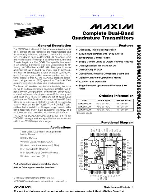
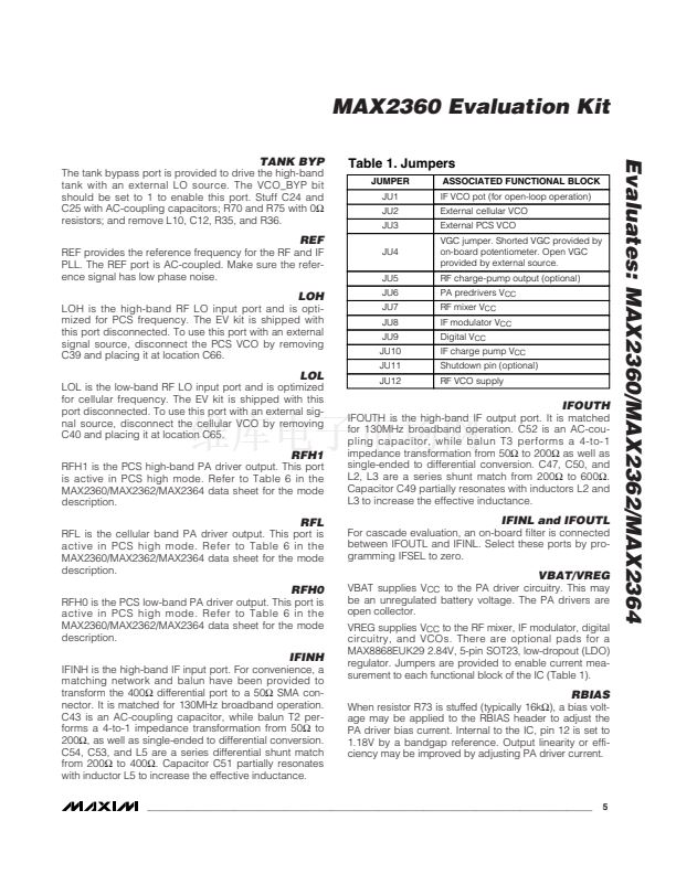
Table 1. Jumpers
JUMPER
JU1
JU2
JU3
JU4
JU5
JU6
JU7
JU8
JU9
JU10
JU11
JU12
ASSOCIATED FUNCTIONAL BLOCK
IF VCO pot (for open-loop operation)
External cellular VCO
External PCS VCO
VGC jumper. Shorted VGC provided by
on-board potentiometer. Open VGC
provided by external source.
RF charge-pump output (optional)
PA predrivers V
CC
RF mixer V
CC
IF modulator V
CC
Digital V
CC
IF charge pump V
CC
Shutdown pin (optional)
RF VCO supply
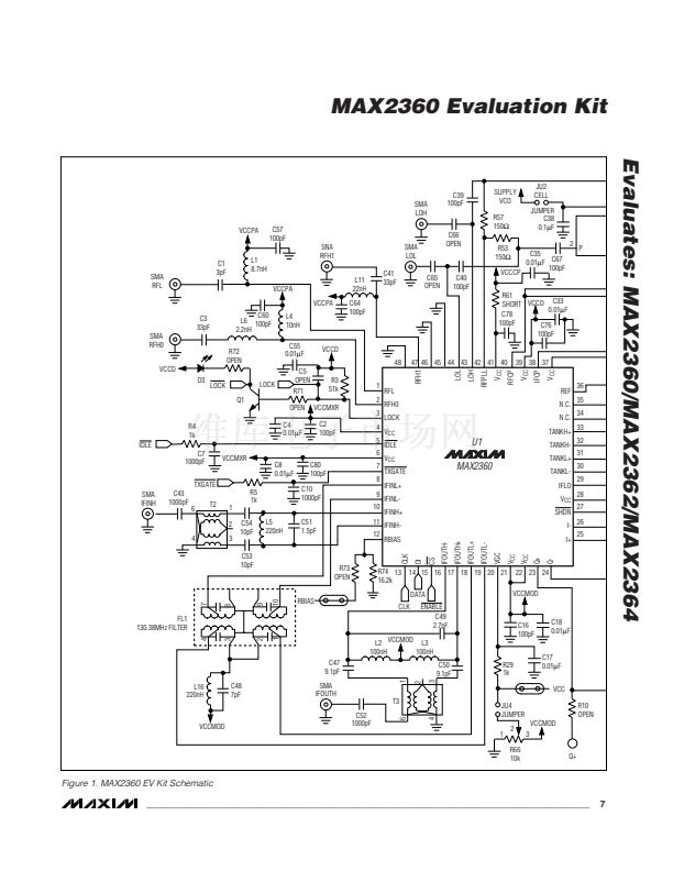
REF
REF provides the reference frequency for the RF and IF
PLL. The REF port is AC-coupled. Make sure the refer-
ence signal has low phase noise.
LOH
LOH is the high-band RF LO input port and is opti-
mized for PCS frequency. The EV kit is shipped with
this port disconnected. To use this port with an external
signal source, disconnect the PCS VCO by removing
C39 and placing it at location C66.
LOL
LOL is the low-band RF LO input port and is optimized
for cellular frequency. The EV kit is shipped with this
port disconnected. To use this port with an external sig-
nal source, disconnect the cellular VCO by removing
C40 and placing it at location C65.
IFOUTH
IFOUTH is the high-band IF output port. It is matched
for 130MHz broadband operation. C52 is an AC-cou-
pling capacitor, while balun T3 performs a 4-to-1
impedance transformation from 50鈩?to 200鈩?as well as
single-ended to differential conversion. C47, C50, and
L2, L3 are a series shunt match from 200鈩?to 600鈩?
Capacitor C49 partially resonates with inductors L2 and
L3 to increase the effective inductance.
RFH1
RFH1 is the PCS high-band PA driver output. This port
is active in PCS high mode. Refer to Table 6 in the
MAX2360/MAX2362/MAX2364 data sheet for the mode
description.
RFL
RFL is the cellular band PA driver output. This port is
active in PCS high mode. Refer to Table 6 in the
MAX2360/MAX2362/MAX2364 data sheet for the mode
description.
IFINL and IFOUTL
For cascade evaluation, an on-board filter is connected
between IFOUTL and IFINL. Select these ports by pro-
gramming IFSEL to zero.
VBAT/VREG
VBAT supplies V
CC
to the PA driver circuitry. This may
be an unregulated battery voltage. The PA drivers are
open collector.
VREG supplies V
CC
to the RF mixer, IF modulator, digital
circuitry, and VCOs. There are optional pads for a
MAX8868EUK29 2.84V, 5-pin SOT23, low-dropout (LDO)
regulator. Jumpers are provided to enable current mea-
surement to each functional block of the IC (Table 1).
RFH0
RFH0 is the PCS low-band PA driver output. This port is
active in PCS high mode. Refer to Table 6 in the
MAX2360/MAX2362/MAX2364 data sheet for the mode
description.
IFINH
IFINH is the high-band IF input port. For convenience, a
matching network and balun have been provided to
transform the 400鈩?differential port to a 50鈩?SMA con-
nector. It is matched for 130MHz broadband operation.
C43 is an AC-coupling capacitor, while balun T2 per-
forms a 4-to-1 impedance transformation from 50鈩?to
200鈩? as well as single-ended to differential conversion.
C54, C53, and L5 are a series differential shunt match
from 200鈩?to 400鈩? Capacitor C51 partially resonates
with inductor L5 to increase the effective inductance.
RBIAS
When resistor R73 is stuffed (typically 16k鈩?, a bias volt-
age may be applied to the RBIAS header to adjust the
PA driver bias current. Internal to the IC, pin 12 is set to
1.18V by a bandgap reference. Output linearity or effi-
ciency may be improved by adjusting PA driver current.
_______________________________________________________________________________________
5


 1
1
 2
2
 3
3
 4
4
 5
5
 6
6
 7
7
 8
8
 9
9
 10
10
 11
11
