MIC4120/4129
Micrel
loads at high frequency. The package power dissipation limit
can easily be exceeded. Therefore, some attention should
be given to power dissipation when driving low impedance
loads and/or operating at high frequency.
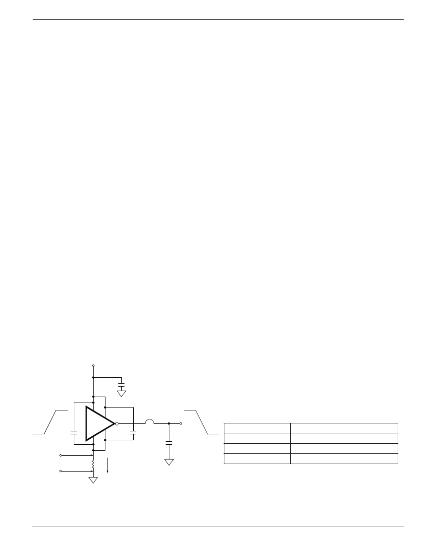
The supply current vs frequency and supply current vs capaci-
tive load characteristic curves aid in determining power dissi-
pation calculations. Table 1 lists the maximum safe operating
frequency for several power supply voltages when driving a
2500pF load. More accurate power dissipation 铿乬ures can
be obtained by summing the three dissipation sources.
Given the power dissipation in the device, and the thermal
resistance of the package, junction operating temperature
for any ambient is easy to calculate. For example, the ther-
mal resistance of the 8-pin EPAD MSOP package, from the
data sheet, is 60掳C/W. In a 25掳C ambient, then, using a
maximum junction temperature of 150掳C, this package will
dissipate 2W.
Accurate power dissipation numbers can be obtained by sum-
ming the three sources of power dissipation in the device:
鈥?Load Power Dissipation (P
L
)
鈥?Quiescent power dissipation (P
Q
)
鈥?Transition power dissipation (P
T
)
Calculation of load power dissipation differs depending on
whether the load is capacitive, resistive or inductive.
Resistive Load Power Dissipation
Dissipation caused by a resistive load can be calculated
as:
P
L
= I
2
R
O
D
where:
I = the current drawn by the load
R
O
= the output resistance of the driver when the output
is high, at the power supply voltage used. (See data
sheet)
D = fraction of time the load is conducting (duty cycle)
Input Stage
The input voltage level of the 4129 changes the quiescent
supply current. The N channel MOSFET input stage transistor
drives a 450碌A current source load. With a logic 鈥?鈥?input, the
maximum quiescent supply current is 450碌A. Logic 鈥?鈥?input
level signals reduce quiescent current to 55碌A maximum.
The MIC4120/4129 input is designed to provide hysteresis.
This provides clean transitions, reduces noise sensitivity,
and minimizes output stage current spiking when changing
states. Input voltage threshold level is approximately 1.5V,
making the device TTL compatible over the 4 .5V to 20V
operating supply voltage range. Input current is less than
10碌A over this range.
The MIC4129 can be directly driven by the MIC9130,
MIC3808, MIC38HC42 and similar switch mode power
supply integrated circuits. By of铿俹ading the power-driving
duties to the MIC4120/4129, the power supply controller can
operate at lower dissipation. This can improve performance
and reliability.
The input can be greater than the
+
V
S
supply, however, current
will 铿俹w into the input lead. The propagation delay for T
D2
will increase to as much as 400ns at room temperature. The
input currents can be as high as 30mA p-p (6.4mA
RMS
) with
the input, 6 V greater than the supply voltage. No damage
will occur to MIC4120/4129 however, and it will not latch.
The input appears as a 7pF capacitance, and does not change
even if the input is driven from an AC source. Care should be
taken so that the input does not go more than 5 volts below
the negative rail.
Power Dissipation
CMOS circuits usually permit the user to ignore power dis-
sipation. Logic families such as 4000 and 74C have outputs
which can only supply a few milliamperes of current, and even
shorting outputs to ground will not force enough current to
destroy the device. The MIC4120/4129 on the other hand,
can source or sink several amperes and drive large capacitive
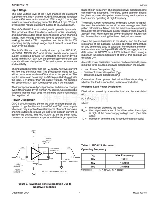
+18 V
WIMA
MK22
1 碌F
5.0V
18 V
Table 1: MIC4129 Maximum
Operating Frequency
0V
1
8
MIC4121
6, 7
TEK CURREN T
P ROBE 6 3 0 2
0V
0.1碌 F
LOGIC锟?frac12;
GROUND
POWER锟?frac12;
GROUND
4
5
0.1碌F
2,500 pF
POLYCARBONATE
6 AMPS
20V
15V
10V
Conditions:
V
S
Max Frequency
1MHz
1.5MHz
3.5MHz
T
A
= 25掳C, 3. C
L
= 2500pF
PC TRACE RESISTANCE = 0.05
鈩?/div>
Figure 3. Switching Time Degradation Due to
Negative Feedback
December 2004
7
M9999-123104


 1
1
 2
2
 3
3
 4
4
 5
5
 6
6
 7
7
 8
8
 9
9
 10
10
 11
11
