


电解电容寿命纹波电流测试
出处:gdengp 发布于:2011-08-29 14:13:18
1. 工作原理/Working principle
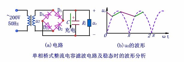

★ 当U2为正半周并且数值大于电容两端电压Uc时,二极管D1和D3管导通,D2和D4管截止,电流一路流经负载电阻RL,另一路对电容C充电。当Uc>U2,导致D1和D3管反向偏置而截止,电容通过负载电阻RL放电,Uc按指数规律缓慢下降。
★ The diode D1&D3 work, D2&D4 cut off, the current flows through the load resistance RL in a loop and charge the capacitor C up when U2 in the positive half circuit and its value exceeding the voltage Uc which is parallel connected in the two terminals of capacitor. When Uc exceeds U2, and causes the diode D1&D3 cut off, the capacitor discharge through the load resistance RL and Uc decline slowly according to the principle of index function.
★ 当U2为负半周幅值变化到恰好大于Uc时,D2和D4因加正向电压变为导通状态,U2再次对C充电,Uc上升到U2的峰值后又开始下降;下降到一定数值时D2和D4变为截止,C对RL放电,Uc按指数规律下降;放电到一定数值时D1和D3变为导通,重复上述过程。
★ As the same reason , when U2 in the negative half circuit and the amplitude is even changed to exceed Uc ,the diode D2&D4 work due to the positive voltage and U2 charge capacitor C up again. Uc start to decline when it’s voltage rise to the peak value of U2 and to a certain value , the diode D2&D4 cut off , the capacitor C discharge to RL, Uc decline according to the principle of index function again. When the discharge to a certain value, the diode D1&D3 work again and the cycle repeats.
2.测试方法/Test Method
2.1 测试温升计算电容寿命/Life time of capacitor at testing temperature condition
计算寿命公式/ Formula for calculating lifetime :

适用公司/ Corporation suited:Fcon 、KSC、TL、TEAPO、CapXon
2.2 测试纹波电流计算电容寿命/Life time of capacitor at testing ripple current condition
计算寿命公式/ Formula for calculating lifetime:

2.2.1 直接测量电容纹波电流/Direct measure of E-cap ripple current

开关电路中电容纹波电流分析
C1为buck电容,其充电时间受到低频交流输入影响,而放电时间则是受到开关管Q1的高频影响。即A点受到低频交流输入影响,频率为交流频率的2倍,100Hz左右,故A点处所测试出电流为电容C1的低频纹波电流(IL);B点受到高频开关Q1的影响,频率一般为100KHz,故B点所测试出的电流为电容C1的高频纹波电流(IH)。
C1 is the buck capacitor, its charge time lies on the low frequency Vac input, and the discharge time influenced by the high frequency of switching MOSFET Q1. The frequency of position A, lying on the Vac input, is doubled, about 100Hz. And the current flowed through just is the low frequency current of C1; similarly, the frequency of position B, lying on the Q1, is about 100 KHz, and the current is high frequency.
目前对电容纹波计算方法定义为/ The test method defined in our company at present is:

2.2.2 利用低通和高通滤波电路测量纹波电流/Measurement via low pass or high pass filter
对于输入大容量的电容,有低频(100HZ)和高频(开关频率,如100KHZ)两种电流流过,电流的测量必须串一个电流检测电阻去获得,而且低频纹波电流和高频纹波电流应分别测量。
For bulk capacitor, both low frequency (100HZ) and high frequency (switching frequency, say 100 KHz) current are flowing. The current shall be measured with a current sense resistor. As the low and high frequency ripple shall be measured separately.

低通滤波电路

高通滤波电路
低通滤波电路的带宽为0~wc(wc=1/RC),高频滤波电路带宽则为>wc。
The bandwidth of low pass filter is 0~wc(wc=1/RC), and >wc in high pass filter.
★ 在检测电阻上并接一个RC(1k5、0.1uF)电路,(如下图所示)用有效值表测量0.1uF两端的有效电压,即可得低频纹波电流值,此时高频成分已被滤除。
Add an RC (1K5, 0.1uF) across the sense resistor, measure rms voltage across 0.1uF; this will filter out the high frequency, leaving the 100Hz ripple current.

低频纹波电流测试图
★ 在检测电阻上并接一个RC(0.1uF、1K5)电路,(如下图所示),用有效值表测1K5电阻两端的有效值电压,根据I=U/R即可获得高频纹波电流值,此时低频成分已被滤除。
Add a CR (0.1uF, 1K5) across the sense resistor, measure rms voltage across 1K5; this will filter out the low frequency, leaving the switching frequency ripple current. Calculate with I =U/R. (Note: R is 0.1 ohm, not 1K5)

高频纹波电流测试图
上一篇:测试测量行业的技术发展趋势展望
下一篇:测试交流电压和电流
版权与免责声明
凡本网注明“出处:维库电子市场网”的所有作品,版权均属于维库电子市场网,转载请必须注明维库电子市场网,https://www.dzsc.com,违反者本网将追究相关法律责任。
本网转载并注明自其它出处的作品,目的在于传递更多信息,并不代表本网赞同其观点或证实其内容的真实性,不承担此类作品侵权行为的直接责任及连带责任。其他媒体、网站或个人从本网转载时,必须保留本网注明的作品出处,并自负版权等法律责任。
如涉及作品内容、版权等问题,请在作品发表之日起一周内与本网联系,否则视为放弃相关权利。
- 聚合物电容器基础知识2024/9/23 16:53:54
- 通过模型预测控制提高电力驱动的性能2024/9/23 16:07:09
- GaN 和 SiC 转换器的控制器 HIL 测试2024/9/14 14:39:44
- 电流检测布局和故障排除指南2024/9/14 11:49:49
- 测量总谐波失真和所使用的功率因数计算2024/9/13 17:18:59