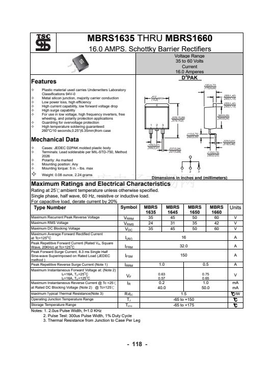
MBRS1635
THRU
MBRS1660
16.0 AMPS. Schottky Barrier Rectifiers
Voltage Range
35 to 60 Volts
Current
16.0 Amperes
Features
Plastic material used carries Underwriters Laboratory
Classifications 94V-0
Metal silicon junction, majority carrier conduction
Low power loss, high efficiency
High current capability, low forward voltage drop
High surge capability
For use in low voltage, high frequency inverters, free
wheeling, and polarity protection applications
Guardring for overvoltage protection
High temperature soldering guaranteed:
260
o
C/10 seconds,0.25鈥?6.35mm)from case
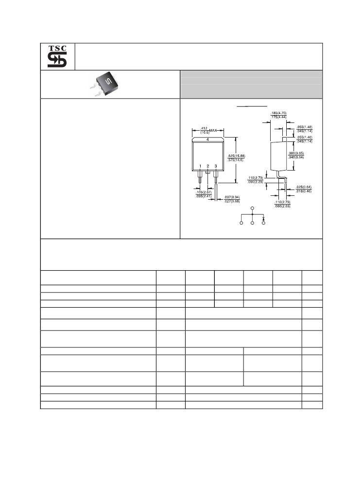
D
2
PAK
Mechanical Data
Cases: JEDEC D2PAK molded plastic body
Terminals: Lead solderable per MIL-STD-750, Method
2026
Polarity: As marked
Mounting position: Any
Mounting torque: 5 in. - lbs. max
Weight: 0.08 ounce, 2.24 grams
1
2
3
Dimensions in inches and (millimeters)
Maximum Ratings and Electrical Characteristics
Rating at 25鈩僡mbient temperature unless otherwise specified.
Single phase, half wave, 60 Hz, resistive or inductive load.
For capacitive load, derate current by 20%
Symbol
MBRS
Type Number
1635
Maximum Recurrent Peak Reverse Voltage
35
V
RRM
Maximum RMS Voltage
24
V
RMS
Maximum DC Blocking Voltage
35
V
DC
Maximum Average Forward Rectified Current
at Tc=125
O
C
Peak Repetitive Forward Current (Rated V
R
, Square
Wave, 20KHz) at Tc=125
o
C
Peak Forward Surge Current, 8.3 ms Single Half
Sine-wave Superimposed on Rated Load (JEDEC
method )
Peak Repetitive Reverse Surge Current (Note 1)
Maximum Instantaneous Forward Voltage at: (Note 2)
I
F
=16A, T
C
=25
o
C
I
F
=16A, T
C
=125
o
C
Maximum Instantaneous Reverse Current @ Tc =25鈩?/div>
at Rated DC Blocking Voltage (Note 2) @ Tc=125鈩?/div>
M
aximum
T
ypical
T
hermal Resistance(Note 3)
MBRS
1645
45
31
45
16
32.0
150
MBRS
1650
50
35
50
MBRS
1660
60
42
60
Units
V
V
V
A
A
A
I
(AV)
I
FRM
I
FSM
I
RRM
V
F
I
R
R
胃
JC
T
J
T
STG
1.0
0.63
0.57
0.5
0.75
0.65
A
V
mA
mA
鈩?W
鈩?/div>
鈩?/div>
0.2
40.0
1.5
-65 to +150
-65 to +175
1.0
50.0
Operating Junction Temperature Range
Storage Temperature Range
Notes: 1. 2.0us Pulse Width, f=1.0 KHz
2. Pulse Test: 300us Pulse Width, 1% Duty Cycle
3. Thermal Resistance from Junction to Case Per Leg
- 118 -


 1
1
 2
2
