PSD835G2
PSD8XX Family
The
PSD835G2
Functional
Blocks
(cont.)
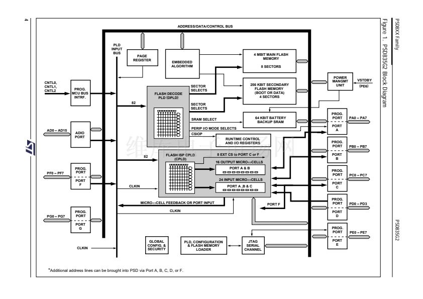
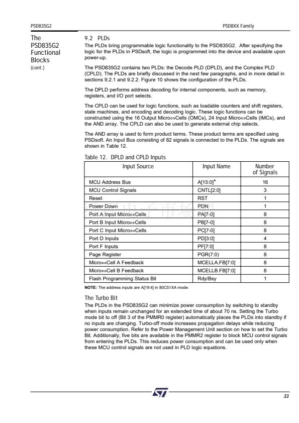
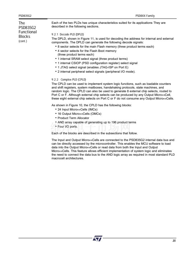
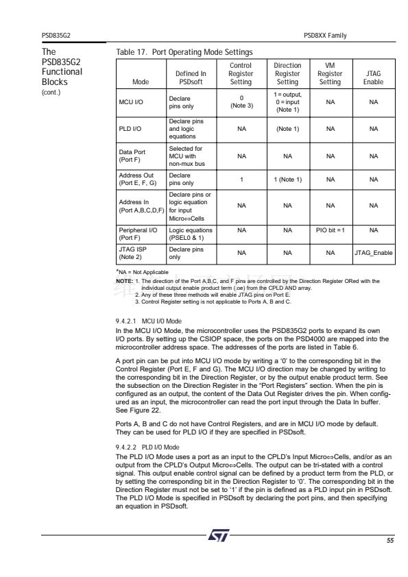
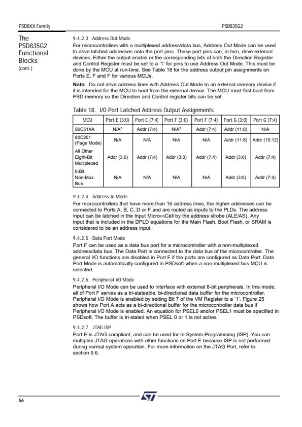
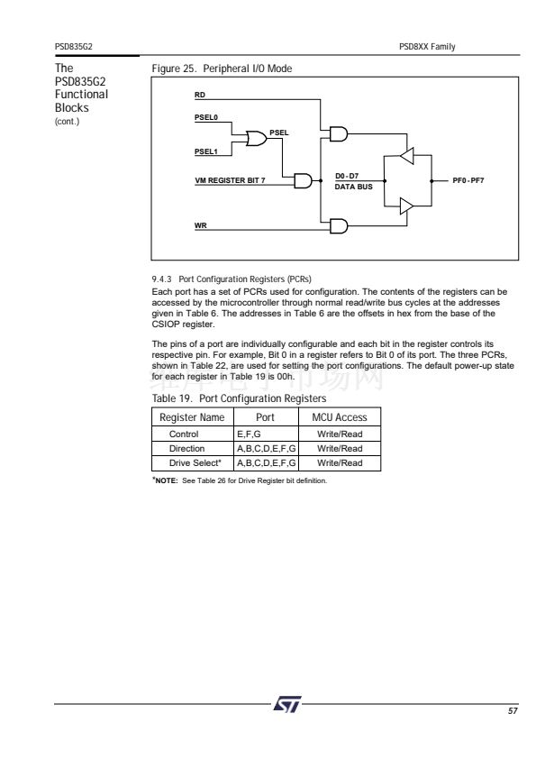
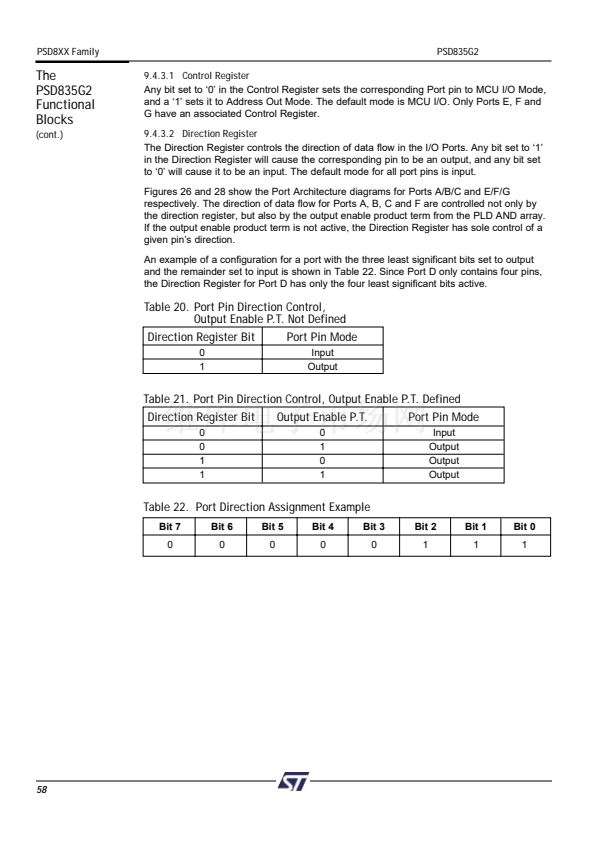
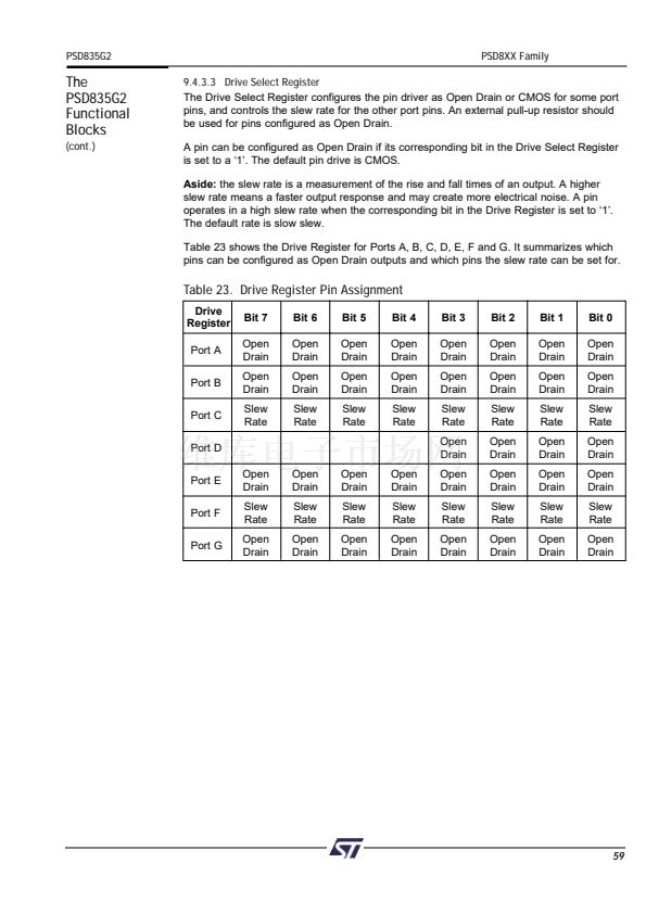
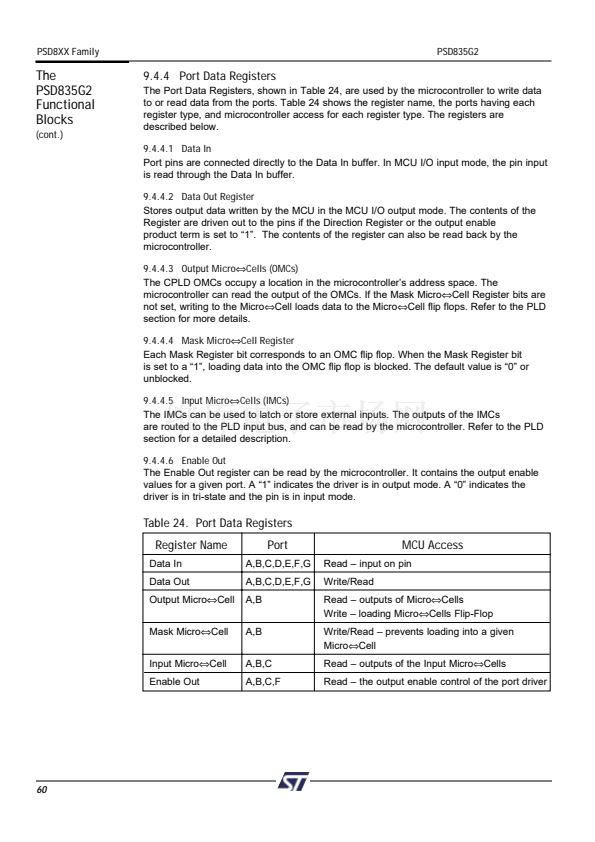
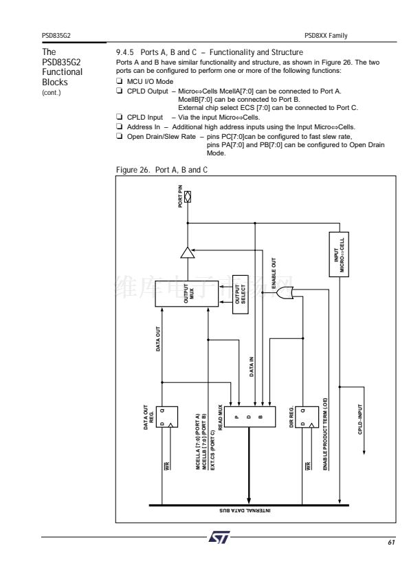
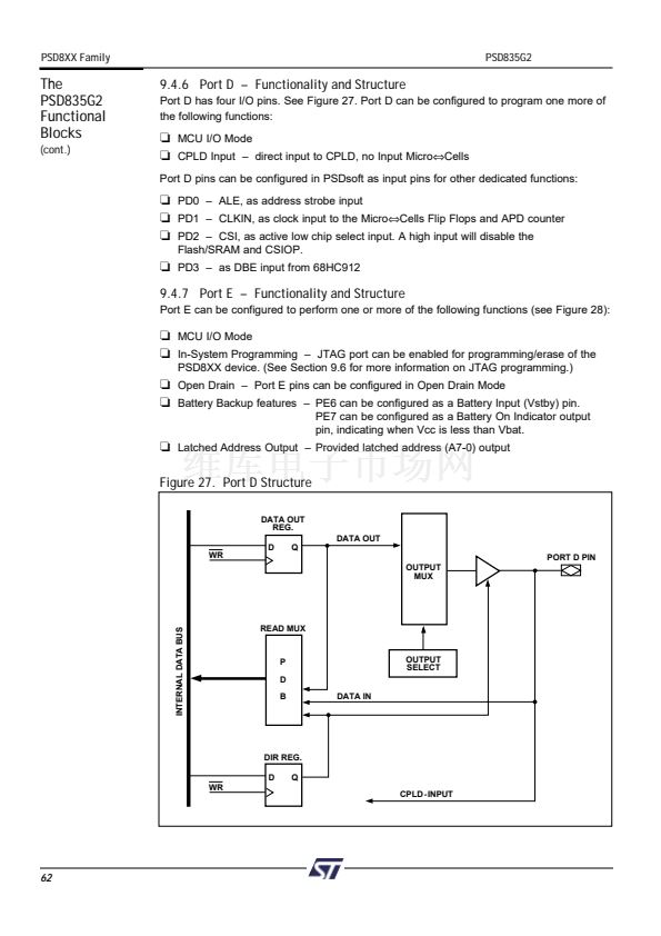
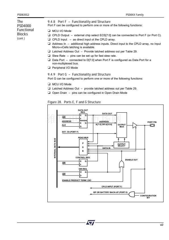
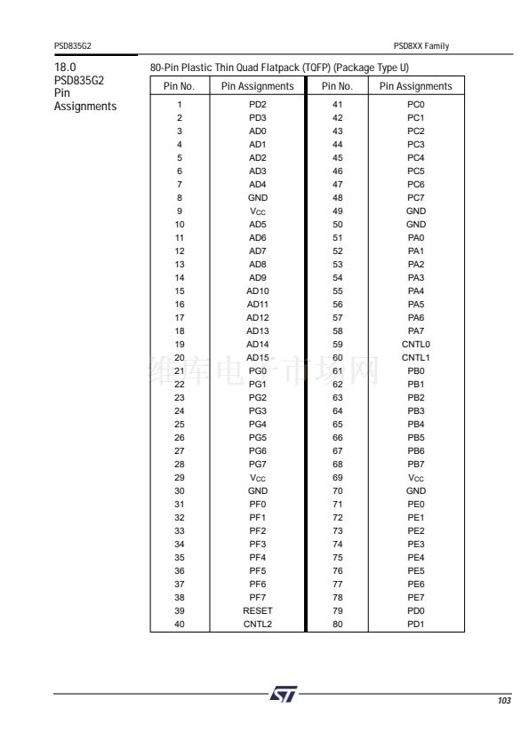
9.2 PLDs
The PLDs bring programmable logic functionality to the PSD835G2. After specifying the
logic for the PLDs in PSDsoft, the logic is programmed into the device and available upon
power-up.
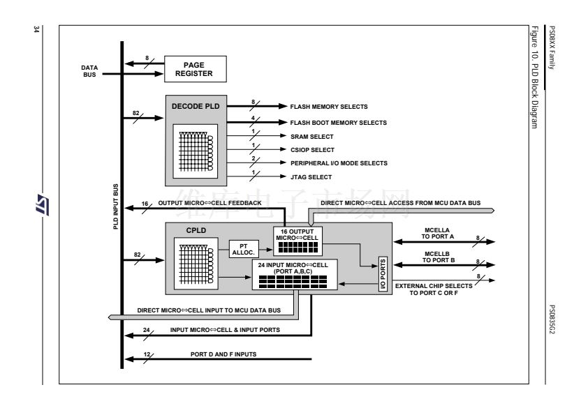
The PSD835G2 contains two PLDs: the Decode PLD (DPLD), and the Complex PLD
(CPLD). The PLDs are briefly discussed in the next few paragraphs, and in more detail in
sections 9.2.1 and 9.2.2. Figure 10 shows the configuration of the PLDs.
The DPLD performs address decoding for internal components, such as memory,
registers, and I/O port selects.
The CPLD can be used for logic functions, such as loadable counters and shift registers,
state machines, and encoding and decoding logic. These logic functions can be
constructed using the 16 Output Micro鈬擟ells (OMCs), 24 Input Micro鈬擟ells (IMCs), and
the AND array. The CPLD can also be used to generate external chip selects.
The AND array is used to form product terms. These product terms are specified using
PSDsoft. An Input Bus consisting of 82 signals is connected to the PLDs. The signals are
shown in Table 12.
Table 12. DPLD and CPLD Inputs
Input Source
MCU Address Bus
MCU Control Signals
Reset
Power Down
Port A Input Micro鈬擟ells
Port B Input Micro鈬擟ells
Port C Input Micro鈬擟ells
Port D Inputs
Port F Inputs
Page Register
Micro鈬擟ell A Feedback
Micro鈬擟ell B Feedback
Flash Programming Status Bit
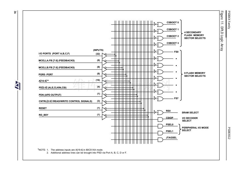
NOTE:
The address inputs are A[19:4] in 80C51XA mode.
Input Name
A[15:0]
*
CNTL[2:0]
RST
PDN
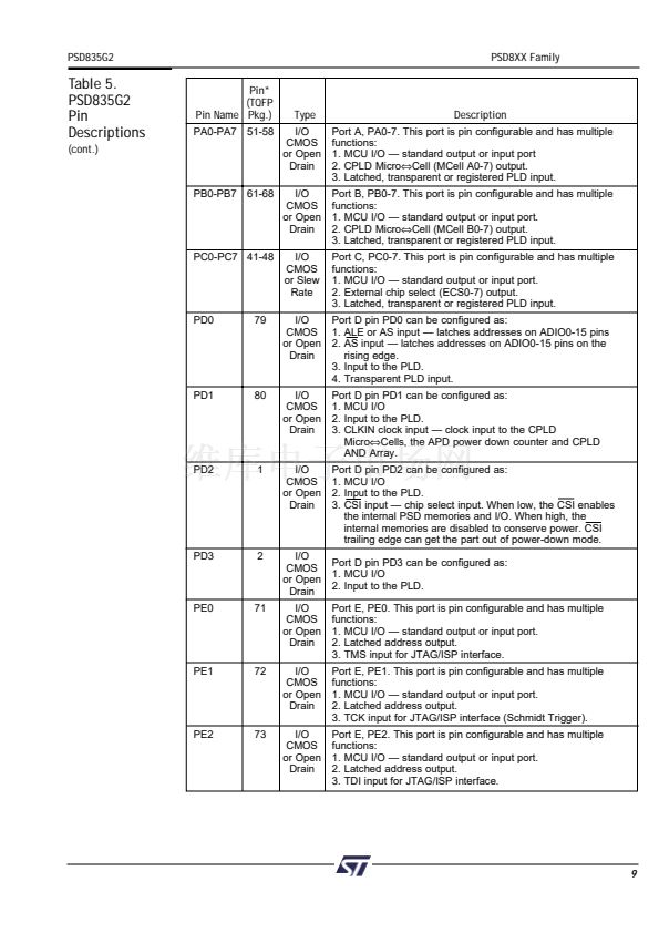
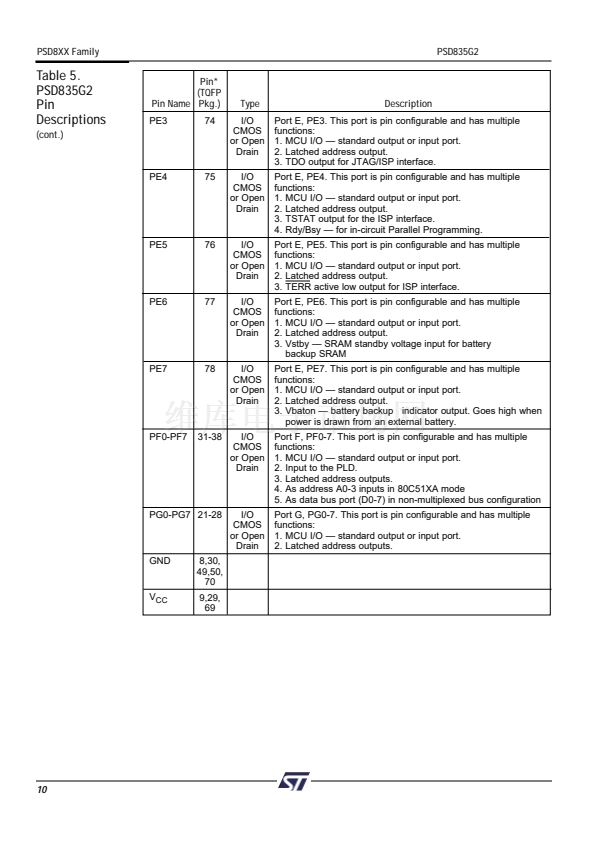
PA[7-0]
PB[7-0]
PC[7-0]
PD[3:0]
PF[7:0]
PGR(7:0)
MCELLA.FB[7:0]
MCELLB.FB[7:0]
Rdy/Bsy
Number
of Signals
16
3
1
1
8
8
8
4
8
8
8
8
1
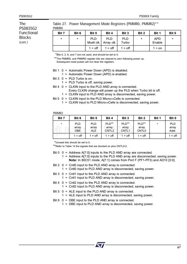
The Turbo Bit
The PLDs in the PSD835G2 can minimize power consumption by switching to standby
when inputs remain unchanged for an extended time of about 70 ns. Setting the Turbo
mode bit to off (Bit 3 of the PMMR0 register) automatically places the PLDs into standby if
no inputs are changing. Turbo-off mode increases propagation delays while reducing
power consumption. Refer to the Power Management Unit section on how to set the Turbo
Bit. Additionally, five bits are available in the PMMR2 register to block MCU control signals
from entering the PLDs. This reduces power consumption and can be used only when
these MCU control signals are not used in PLD logic equations.
33


 1
1
 2
2
 3
3
 4
4
 5
5
 6
6
 7
7
 8
8
 9
9
 10
10
 11
11
 12
12
 13
13
 14
14
 15
15
 16
16
 17
17
 18
18
 19
19
 20
20
 21
21
 22
22
 23
23
 24
24
 25
25
 26
26
 27
27
 28
28
 29
29
 30
30
 31
31
 32
32
 33
33
 34
34
 35
35
 36
36
 37
37
 38
38
 39
39
 40
40
 41
41
 42
42
 43
43
 44
44
 45
45
 46
46
 47
47
 48
48
 49
49
 50
50
 51
51
 52
52
 53
53
 54
54
 55
55
 56
56
 57
57
 58
58
 59
59
 60
60
 61
61
 62
62
 63
63
 64
64
 65
65
 66
66
 67
67
 68
68
 69
69
 70
70
 71
71
 72
72
 73
73
 74
74
 75
75
 76
76
 77
77
 78
78
 79
79
 80
80
 81
81
 82
82
 83
83
 84
84
 85
85
 86
86
 87
87
 88
88
 89
89
 90
90
 91
91
 92
92
 93
93
 94
94
 95
95
 96
96
 97
97
 98
98
 99
99
 100
100
 101
101
 102
102
 103
103
 104
104
 105
105
 106
106
 107
107
 108
108
 109
109
 110
110
