PSD8XX Family
PSD835G2
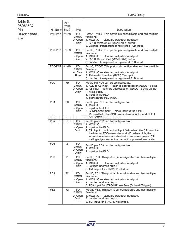
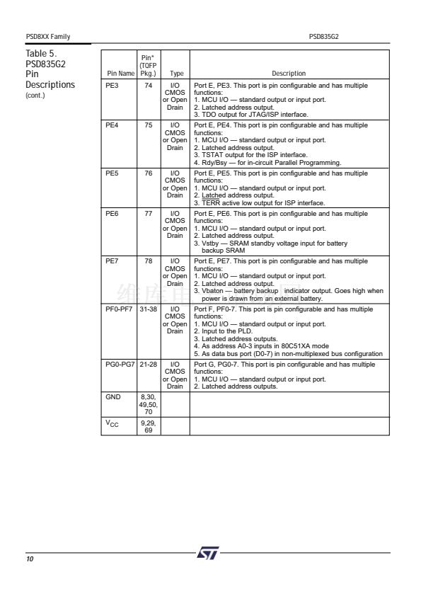
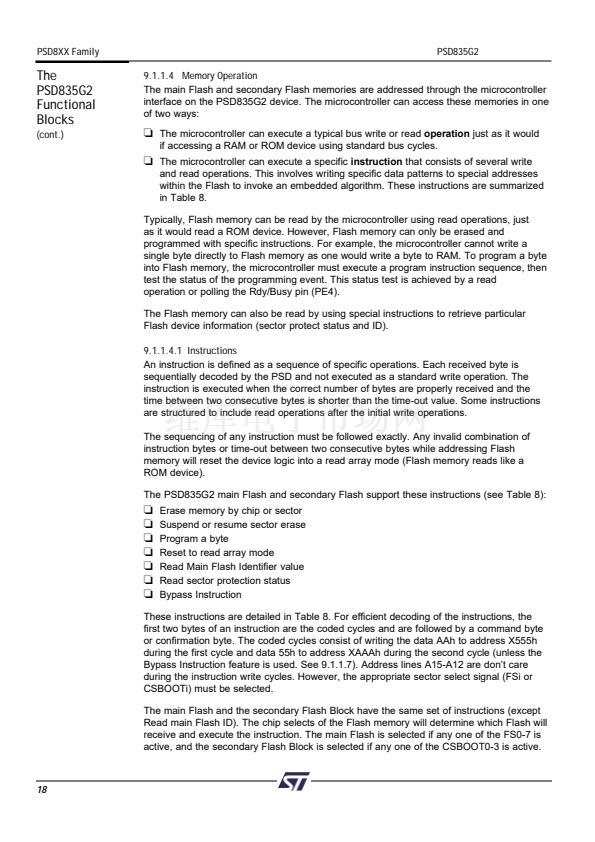
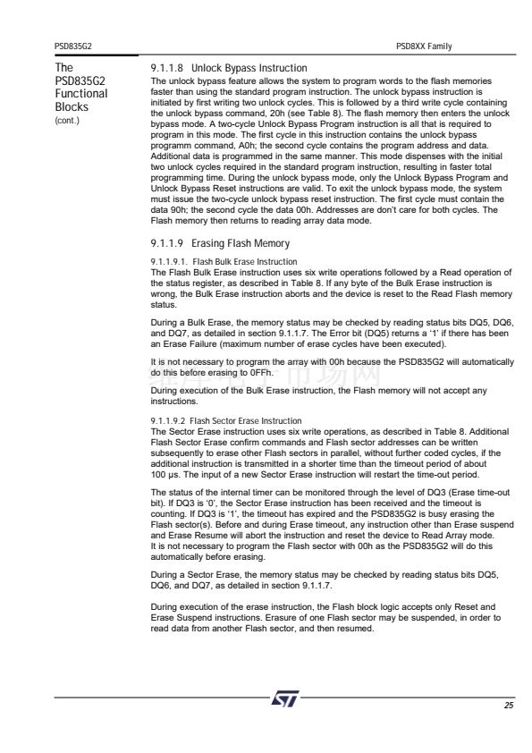
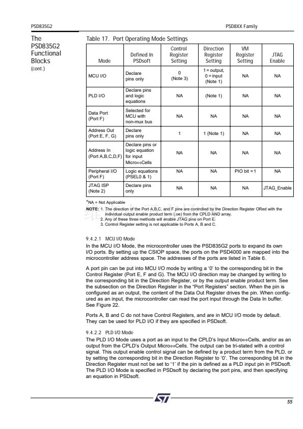
9.4.2.3 Address Out Mode
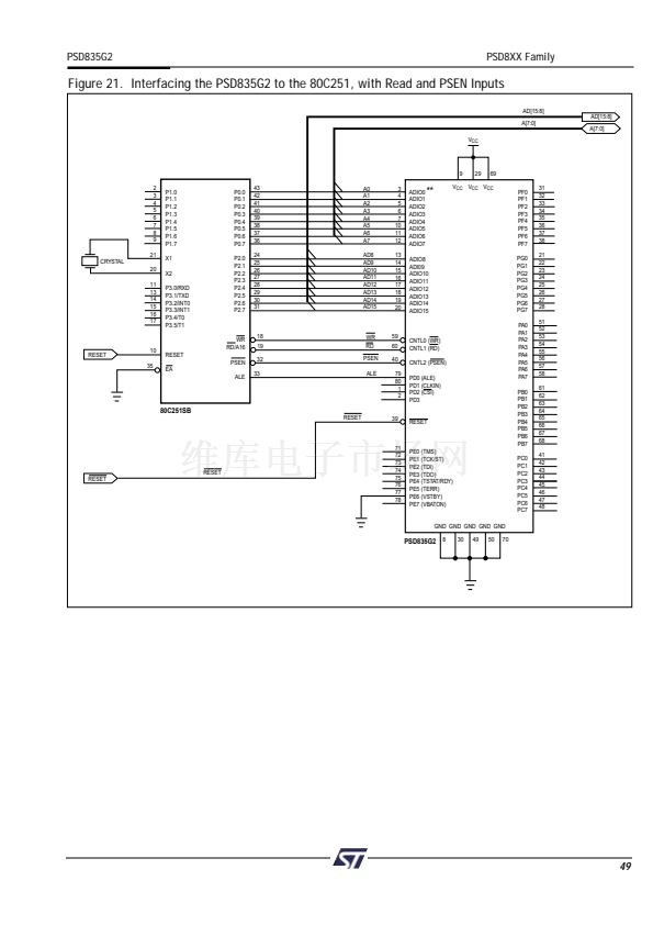
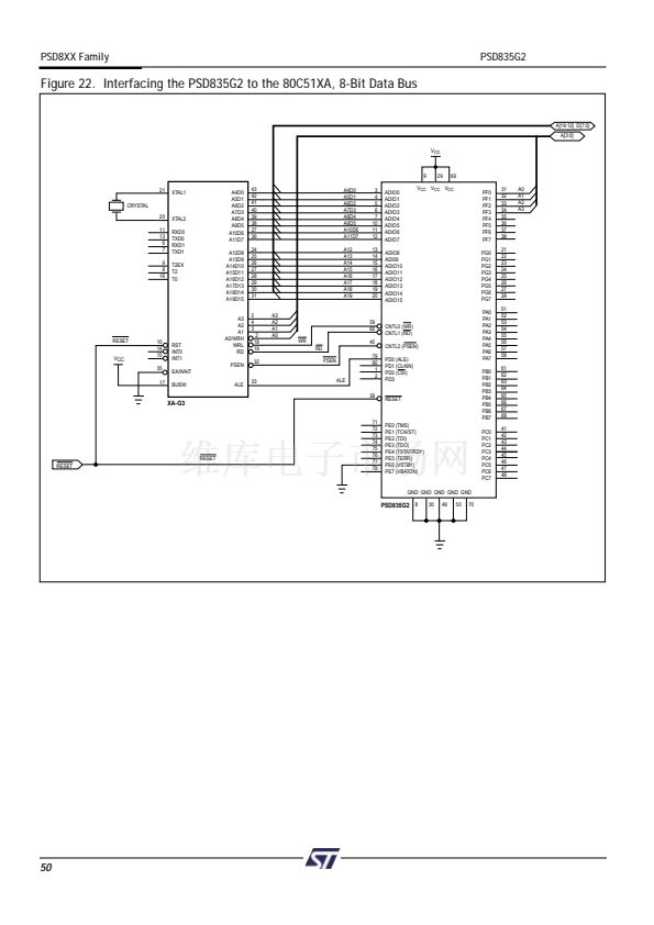
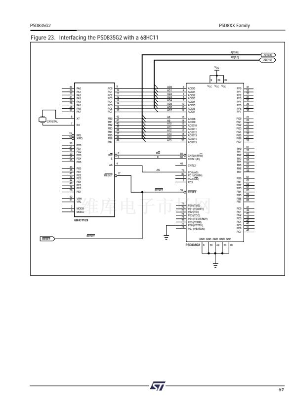
For microcontrollers with a multiplexed address/data bus, Address Out Mode can be used
to drive latched addresses onto the port pins. These port pins can, in turn, drive external
devices. Either the output enable or the corresponding bits of both the Direction Register
and Control Register must be set to a 鈥?鈥?for pins to use Address Out Mode. This must be
done by the MCU at run-time. See Table 18 for the address output pin assignments on
Ports E, F and F for various MCUs.
Note:
Do not drive address lines with Address Out Mode to an external memory device if
it is intended for the MCU to boot from the external device. The MCU must first boot from
PSD memory so the Direction and Control register bits can be set.
The
PSD835G2
Functional
Blocks
(cont.)
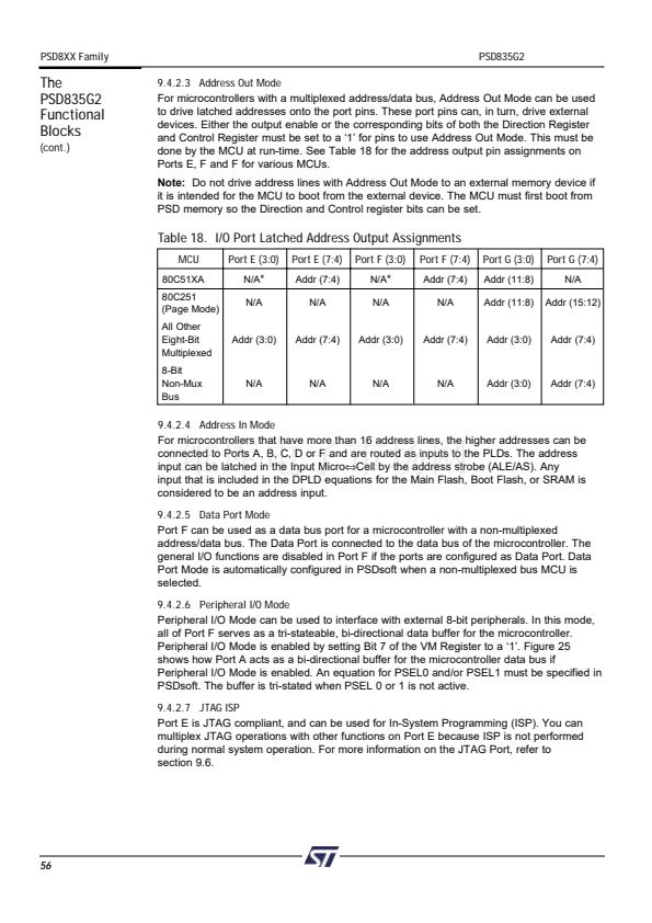
Table 18. I/O Port Latched Address Output Assignments
MCU
80C51XA
80C251
(Page Mode)
All Other
Eight-Bit
Multiplexed
8-Bit
Non-Mux
Bus
Port E (3:0)
N/A
*
N/A
Port E (7:4)
Addr (7:4)
N/A
Port F (3:0)
N/A
*
N/A
Port F (7:4)
Addr (7:4)
N/A
Port G (3:0)
Addr (11:8)
Addr (11:8)
Port G (7:4)
N/A
Addr (15:12)
Addr (3:0)
Addr (7:4)
Addr (3:0)
Addr (7:4)
Addr (3:0)
Addr (7:4)
N/A
N/A
N/A
N/A
Addr (3:0)
Addr (7:4)
9.4.2.4 Address In Mode
For microcontrollers that have more than 16 address lines, the higher addresses can be
connected to Ports A, B, C, D or F and are routed as inputs to the PLDs. The address
input can be latched in the Input Micro鈬擟ell by the address strobe (ALE/AS). Any
input that is included in the DPLD equations for the Main Flash, Boot Flash, or SRAM is
considered to be an address input.
9.4.2.5 Data Port Mode
Port F can be used as a data bus port for a microcontroller with a non-multiplexed
address/data bus. The Data Port is connected to the data bus of the microcontroller. The
general I/O functions are disabled in Port F if the ports are configured as Data Port. Data
Port Mode is automatically configured in PSDsoft when a non-multiplexed bus MCU is
selected.
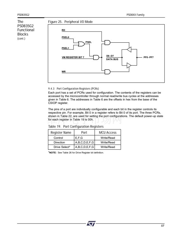
9.4.2.6 Peripheral I/O Mode
Peripheral I/O Mode can be used to interface with external 8-bit peripherals. In this mode,
all of Port F serves as a tri-stateable, bi-directional data buffer for the microcontroller.
Peripheral I/O Mode is enabled by setting Bit 7 of the VM Register to a 鈥?鈥? Figure 25
shows how Port A acts as a bi-directional buffer for the microcontroller data bus if
Peripheral I/O Mode is enabled. An equation for PSEL0 and/or PSEL1 must be specified in
PSDsoft. The buffer is tri-stated when PSEL 0 or 1 is not active.
9.4.2.7 JTAG ISP
Port E is JTAG compliant, and can be used for In-System Programming (ISP). You can
multiplex JTAG operations with other functions on Port E because ISP is not performed
during normal system operation. For more information on the JTAG Port, refer to
section 9.6.
56


 1
1
 2
2
 3
3
 4
4
 5
5
 6
6
 7
7
 8
8
 9
9
 10
10
 11
11
 12
12
 13
13
 14
14
 15
15
 16
16
 17
17
 18
18
 19
19
 20
20
 21
21
 22
22
 23
23
 24
24
 25
25
 26
26
 27
27
 28
28
 29
29
 30
30
 31
31
 32
32
 33
33
 34
34
 35
35
 36
36
 37
37
 38
38
 39
39
 40
40
 41
41
 42
42
 43
43
 44
44
 45
45
 46
46
 47
47
 48
48
 49
49
 50
50
 51
51
 52
52
 53
53
 54
54
 55
55
 56
56
 57
57
 58
58
 59
59
 60
60
 61
61
 62
62
 63
63
 64
64
 65
65
 66
66
 67
67
 68
68
 69
69
 70
70
 71
71
 72
72
 73
73
 74
74
 75
75
 76
76
 77
77
 78
78
 79
79
 80
80
 81
81
 82
82
 83
83
 84
84
 85
85
 86
86
 87
87
 88
88
 89
89
 90
90
 91
91
 92
92
 93
93
 94
94
 95
95
 96
96
 97
97
 98
98
 99
99
 100
100
 101
101
 102
102
 103
103
 104
104
 105
105
 106
106
 107
107
 108
108
 109
109
 110
110
