PSD835G2
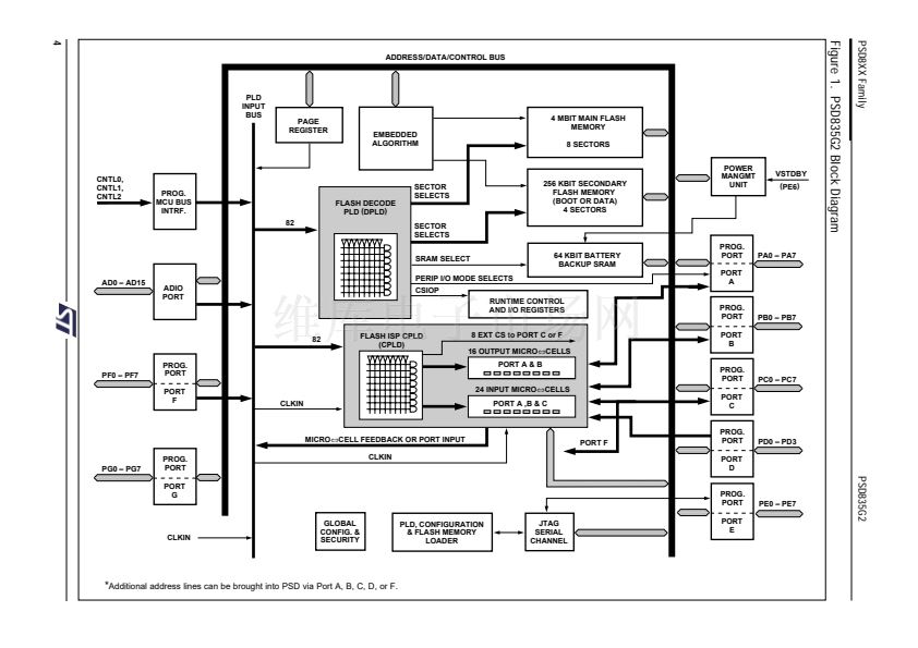
PSD8XX Family
The
PSD835G2
Functional
Blocks
(cont.)
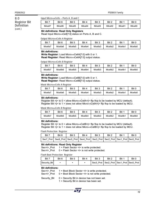
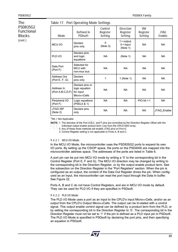
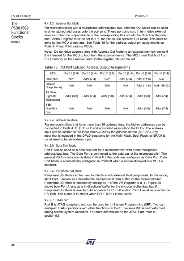
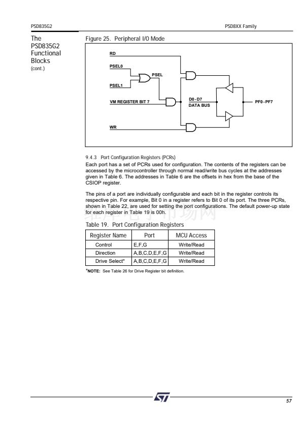
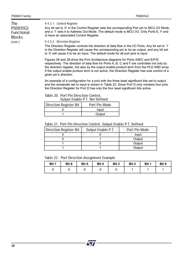
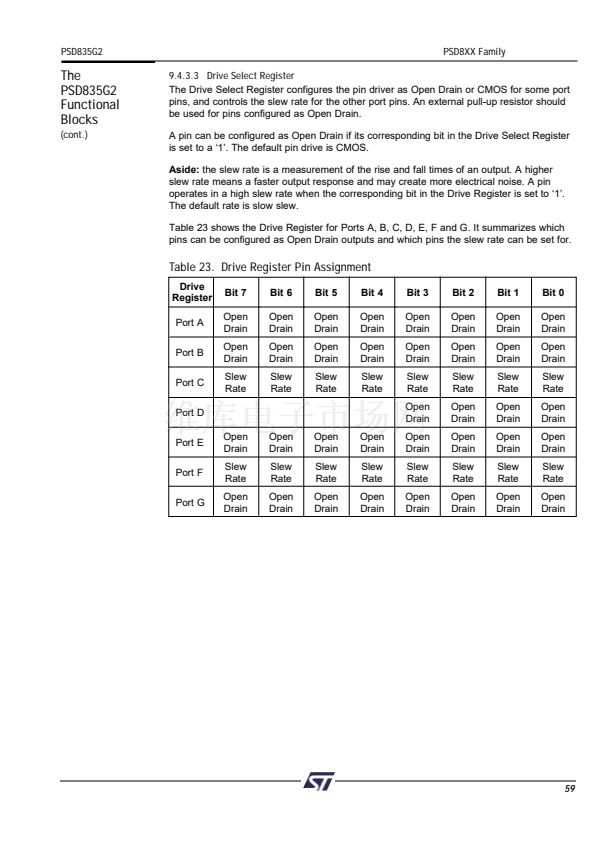
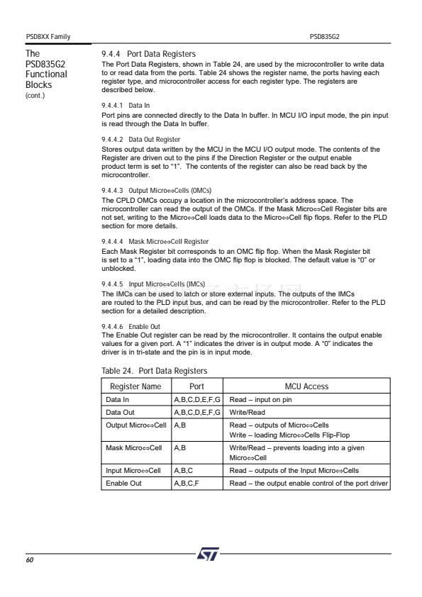
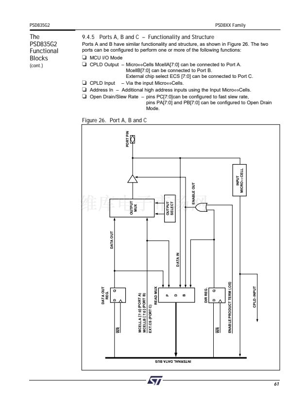
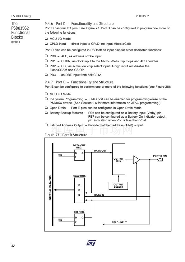
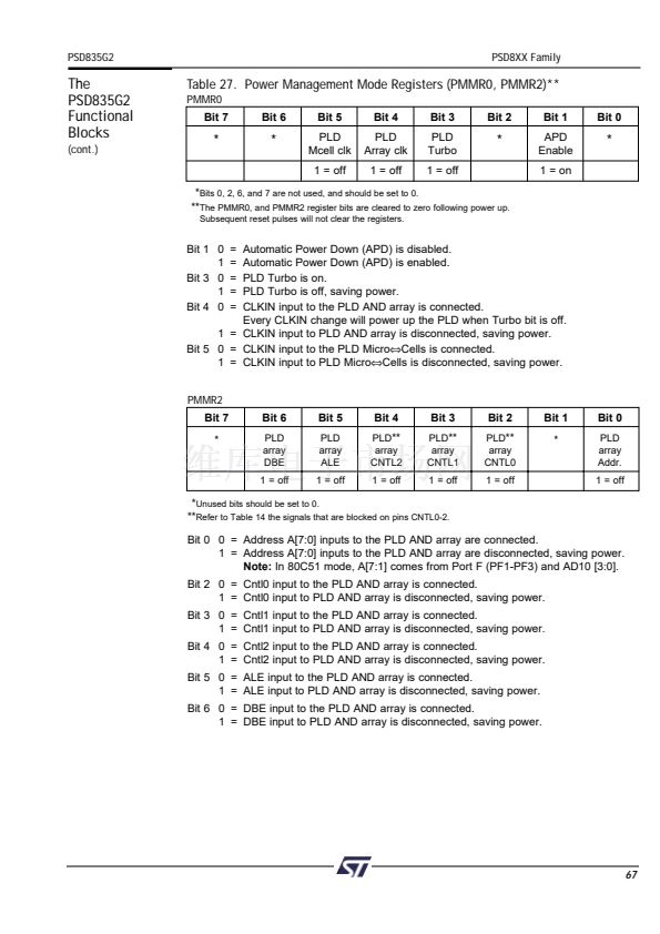
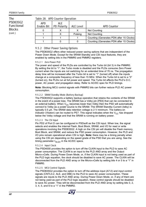
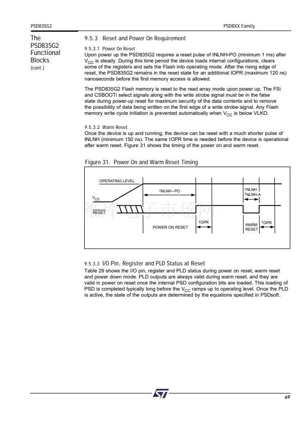
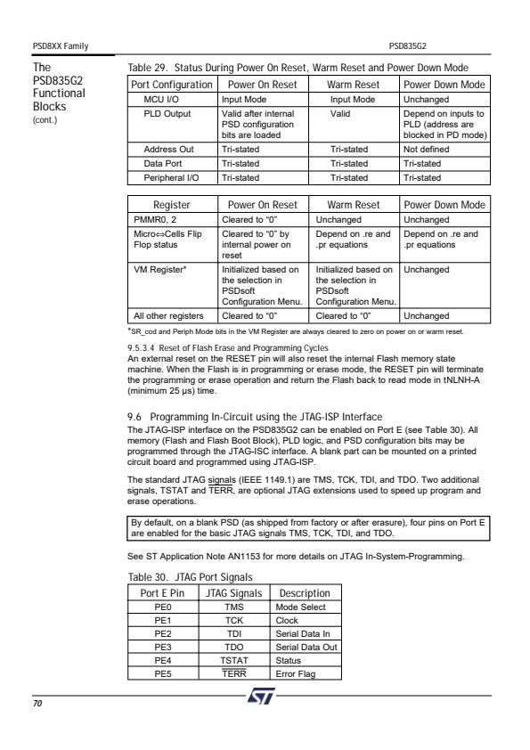
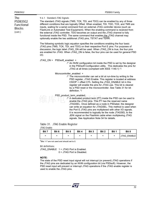
Table 27. Power Management Mode Registers (PMMR0, PMMR2)**
PMMR0
Bit 7
Bit 6
Bit 5
PLD
Mcell clk
1 = off
Bit 4
PLD
Array clk
1 = off
Bit 3
PLD
Turbo
1 = off
Bit 2
Bit 1
APD
Enable
1 = on
Bit 0
*
*
*
*
***
Bits 0, 2, 6, and 7 are not used, and should be set to 0.
***
The PMMR0, and PMMR2 register bits are cleared to zero following power up.
***
Subsequent reset pulses will not clear the registers.
Bit 1 0
1
Bit 3 0
1
Bit 4 0
Automatic Power Down (APD) is disabled.
Automatic Power Down (APD) is enabled.
PLD Turbo is on.
PLD Turbo is off, saving power.
CLKIN input to the PLD AND array is connected.
Every CLKIN change will power up the PLD when Turbo bit is off.
1 = CLKIN input to PLD AND array is disconnected, saving power.
Bit 5 0 = CLKIN input to the PLD Micro鈬擟ells is connected.
1 = CLKIN input to PLD Micro鈬擟ells is disconnected, saving power.
PMMR2
Bit 7
*
Bit 6
PLD
array
DBE
1 = off
=
=
=
=
=
Bit 5
PLD
array
ALE
1 = off
Bit 4
PLD
**
array
CNTL2
1 = off
Bit 3
PLD
**
array
CNTL1
1 = off
Bit 2
PLD
**
array
CNTL0
1 = off
Bit 1
*
Bit 0
PLD
array
Addr.
1 = off
**
Unused bits should be set to 0.
**
Refer to Table 14 the signals that are blocked on pins CNTL0-2.
Bit 0 0 = Address A[7:0] inputs to the PLD AND array are connected.
1 = Address A[7:0] inputs to the PLD AND array are disconnected, saving power.
Note:
In 80C51 mode, A[7:1] comes from Port F (PF1-PF3) and AD10 [3:0].
Bit 2 0 = Cntl0 input to the PLD AND array is connected.
1 = Cntl0 input to PLD AND array is disconnected, saving power.
Bit 3 0 = Cntl1 input to the PLD AND array is connected.
1 = Cntl1 input to PLD AND array is disconnected, saving power.
Bit 4 0 = Cntl2 input to the PLD AND array is connected.
1 = Cntl2 input to PLD AND array is disconnected, saving power.
Bit 5 0 = ALE input to the PLD AND array is connected.
1 = ALE input to PLD AND array is disconnected, saving power.
Bit 6 0 = DBE input to the PLD AND array is connected.
1 = DBE input to PLD AND array is disconnected, saving power.
67


 1
1
 2
2
 3
3
 4
4
 5
5
 6
6
 7
7
 8
8
 9
9
 10
10
 11
11
 12
12
 13
13
 14
14
 15
15
 16
16
 17
17
 18
18
 19
19
 20
20
 21
21
 22
22
 23
23
 24
24
 25
25
 26
26
 27
27
 28
28
 29
29
 30
30
 31
31
 32
32
 33
33
 34
34
 35
35
 36
36
 37
37
 38
38
 39
39
 40
40
 41
41
 42
42
 43
43
 44
44
 45
45
 46
46
 47
47
 48
48
 49
49
 50
50
 51
51
 52
52
 53
53
 54
54
 55
55
 56
56
 57
57
 58
58
 59
59
 60
60
 61
61
 62
62
 63
63
 64
64
 65
65
 66
66
 67
67
 68
68
 69
69
 70
70
 71
71
 72
72
 73
73
 74
74
 75
75
 76
76
 77
77
 78
78
 79
79
 80
80
 81
81
 82
82
 83
83
 84
84
 85
85
 86
86
 87
87
 88
88
 89
89
 90
90
 91
91
 92
92
 93
93
 94
94
 95
95
 96
96
 97
97
 98
98
 99
99
 100
100
 101
101
 102
102
 103
103
 104
104
 105
105
 106
106
 107
107
 108
108
 109
109
 110
110
