CS5320/21/22
2.4 Voltage Reference
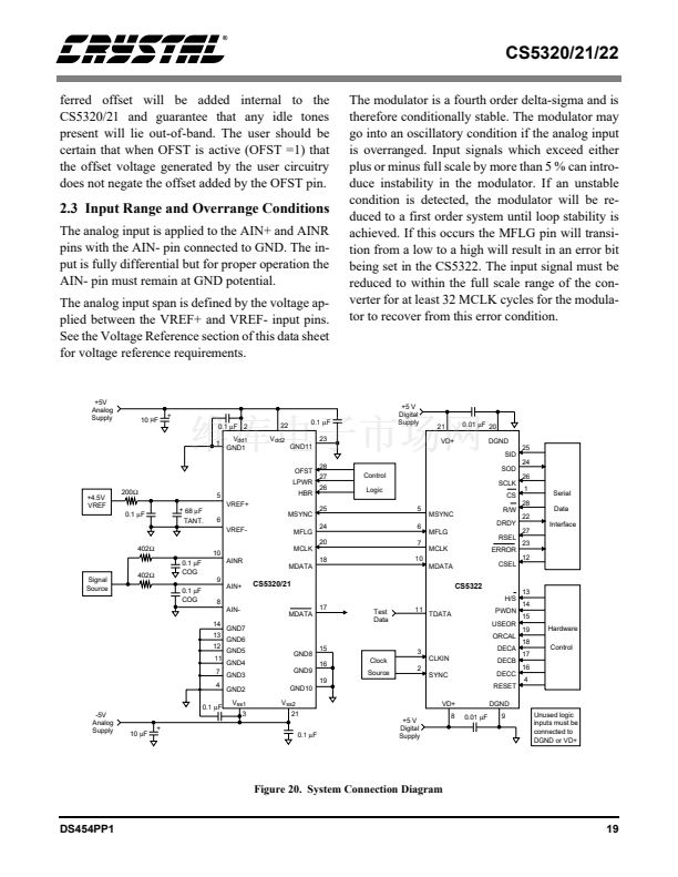
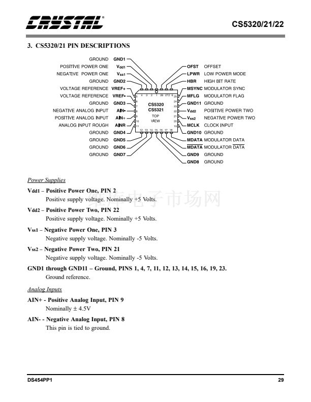
The CS5320/21 is designed to operate with a volt-
age reference in the range of 4.0 to 4.5 volts. The
voltage reference is applied to the VREF+ pin with
the VREF- pin connected to the GND. A 4.5 V ref-
erence will result in the best S/N performance but
most 4.5 V references require a power supply volt-
age greater than 5.0 V for operation. A 4.0 V refer-
ence can be used for those applications which must
operate from only 5.0 V supplies, but will yield a
S/N slightly lower (1-2 dB) than when using a 4.5
V reference. The voltage reference should be de-
signed to yield less than 2
碌V
rms of noise in band
at the VREF+ pin of the CS5320/21. The CS5322
filter selection will determine the bandwidth over
which the voltage reference noise will affect the
CS5320/21/22 dynamic range.
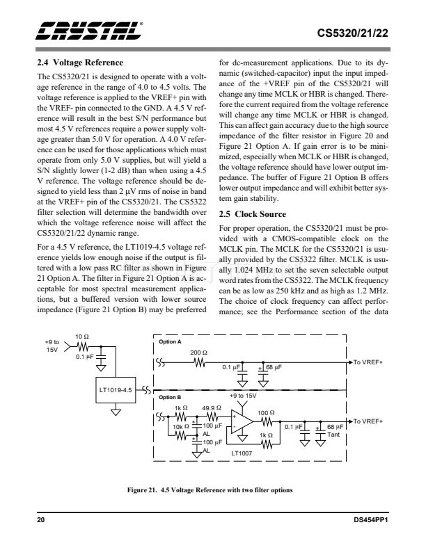
For a 4.5 V reference, the LT1019-4.5 voltage ref-
erence yields low enough noise if the output is fil-
tered with a low pass RC filter as shown in Figure
21 Option A. The filter in Figure 21 Option A is ac-
ceptable for most spectral measurement applica-
tions, but a buffered version with lower source
impedance (Figure 21 Option B) may be preferred
10
鈩?/div>
0.1
碌
F
for dc-measurement applications. Due to its dy-
namic (switched-capacitor) input the input imped-
ance of the +VREF pin of the CS5320/21 will
change any time MCLK or HBR is changed. There-
fore the current required from the voltage reference
will change any time MCLK or HBR is changed.
This can affect gain accuracy due to the high source
impedance of the filter resistor in Figure 20 and
Figure 21 Option A. If gain error is to be mini-
mized, especially when MCLK or HBR is changed,
the voltage reference should have lower output im-
pedance. The buffer of Figure 21 Option B offers
lower output impedance and will exhibit better sys-
tem gain stability.
2.5 Clock Source
For proper operation, the CS5320/21 must be pro-
vided with a CMOS-compatible clock on the
MCLK pin. The MCLK for the CS5320/21 is usu-
ally provided by the CS5322 filter. MCLK is usu-
ally 1.024 MHz to set the seven selectable output
word rates from the CS5322. The MCLK frequency
can be as low as 250 kHz and as high as 1.2 MHz.
The choice of clock frequency can affect perfor-
mance; see the Performance section of the data
+9 to
15V
Option A
200
鈩?/div>
0.1
碌
F
+ 68
碌
F
To VREF+
LT1019-4.5
Option B
+9 to 15V
1k
鈩?/div>
10k
鈩?/div>
+
49.9
鈩?/div>
+
100
碌
F
AL
100
碌
F
AL
-
100
鈩?/div>
0.1
碌
F
1k
鈩?/div>
+
+
68
碌
F
Tant
To VREF+
LT1007
Figure 21. 4.5 Voltage Reference with two filter options
20
DS454PP1
CS5321-BL1相关型号PDF文件下载
-
型号
版本
描述
厂商
下载
-
英文版
RF COILS
-
英文版
Sumida Corporation [RF COILS < SMD Type: CS Series>]
-
英文版
Three-Phase Buck Controller with Integrated Gate Drivers an...
ONSEMI
-
英文版
Three-PhaseBuck Controller withIntegrated Gate Drivers andPo...
-
英文版
Two-Phase Buck Controllerwith Integrated GateDrivers and 4-B...
-
英文版
Three-Phase BuckController with IntegratedGate Drivers
-
英文版
Three-Phase SynchronousSwitching Step-DownController with Si...
-
英文版
Four-Phase VRM 9.0 Buck Controller
-
英文版
Two-Phase PWM Controllerwith Integrated GateDrivers for VRM ...
-
英文版
Two-Phase PWM Controller with Integrated Gate Drivers for VR...
-
英文版
16-Bit, 20 kHz Oversampling A/D Converter
CIRRUS
-
英文版
-
英文版
-
英文版
24-Bit Variable Bandwidth A/D Converter Chipset
CIRRUS
-
英文版
-
英文版
-
英文版
24-Bit Variable Bandwidth A/D Converter Chipset
CIRRUS
-
英文版
-
英文版
24-Bit Variable Bandwidth A/D Converter Chipset
CIRRUS
-
英文版
Two-Phase Buck Controllerwith Integrated GateDrivers and 5-B...


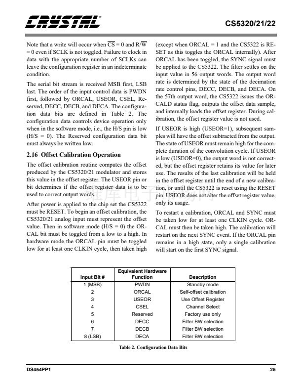
 1
1
 2
2
 3
3
 4
4
 5
5
 6
6
 7
7
 8
8
 9
9
 10
10
 11
11
 12
12
 13
13
 14
14
 15
15
 16
16
 17
17
 18
18
 19
19
 20
20
 21
21
 22
22
 23
23
 24
24
 25
25
 26
26
 27
27
 28
28
 29
29
 30
30
 31
31
 32
32
 33
33
 34
34
 35
35
 36
36
 37
37
 38
38
