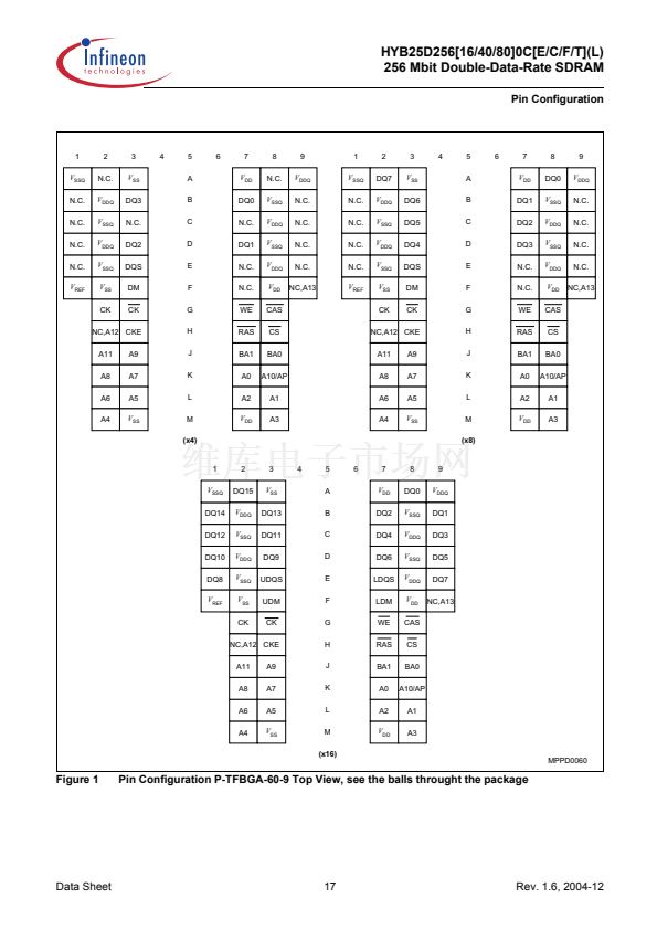
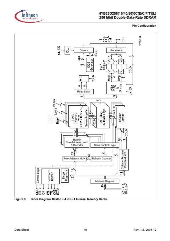
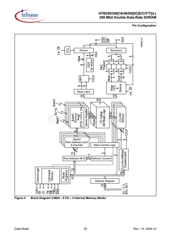
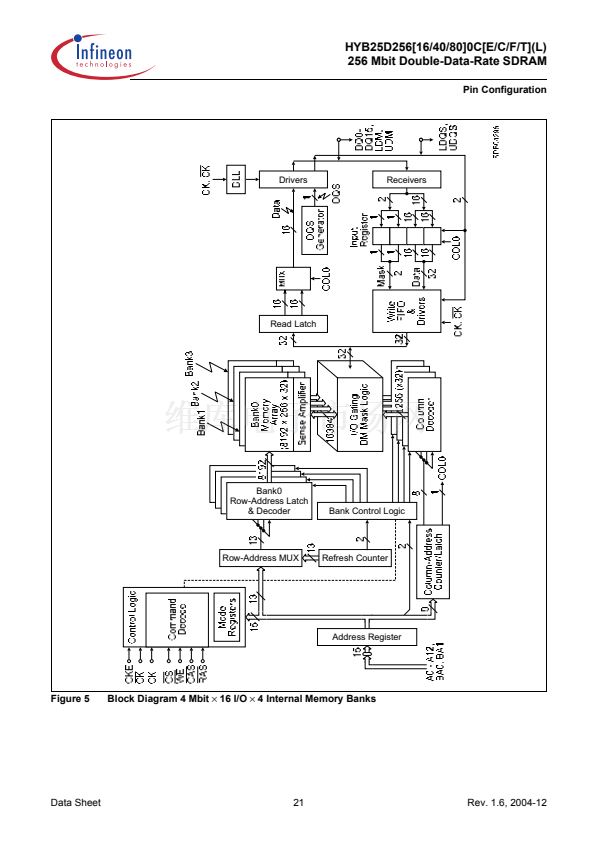
HYB25D256[16/40/80]0C[E/C/F/T](L)
256 Mbit Double-Data-Rate SDRAM
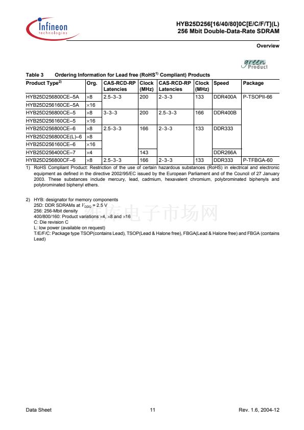
System Characteristics for DDR SDRAMs
6
System Characteristics for DDR SDRAMs
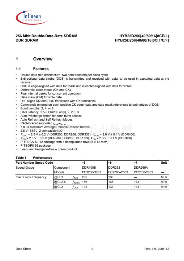
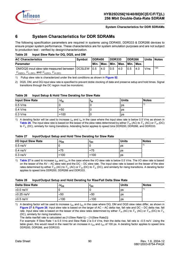
The following specification parameters are required in systems using DDR400, DDR333 & DDR266 devices to
ensure proper system performance. These characteristics are for system simulation purposes and are not subject
to production test - verified by design/characterization.
Table 25
Parameter
Input Slew Rate for DQ, DQS, and DM
Symbol
DDR400
4.0
DDR333
0.5
4.0
DDR266
0.5
4.0
Units Notes
V/ns
1)2)
AC Characteristics
Min. Max. Min. Max. Min. Max.
DM/DQS inout slew rate measured berween DCSLEW 0.5
V
IH(DC)
,
V
IL (DC)
, and
V
IL(DC)
,
V
IH (DC)
1)
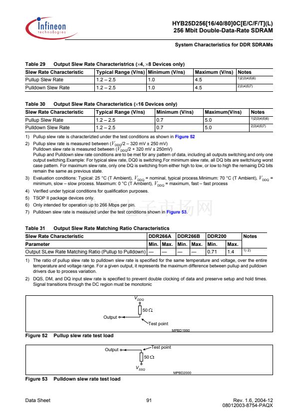
Pullup slew rate is characterized under the test conditions as shown in
Figure 52.
2) DQS, DM, amd DQ input slew rate is specified to prevent doble clocking of data and preserve setup and hold times. Signal
transitions through the DC region must be monotonic.
Table 26
0.5 V/ns
0.4 V/ns
0.3 V/ns
Input Setup & Hold Time Derating for Slew Rate
鈭?/div>
t
IS
0
+50
+100
Input Slew Rate
t
IH
0
0
0
Units
ps
ps
ps
Notes
1)
1) A derating factor will be used to increase
t
IS
and
t
IH
in the case where the input slew rate is below 0.5 V/ns as shown in
Table 26.
The input slew rate is based on the lesser of the slew rates determined by either
V
IH
(AC) to
V
IL
(AC) or
V
IH
(DC)
to
V
IL
(DC), similarly for rising transitions. Aderating factor applies to speed bins DDR200, DDR266, and DDR333.
Table 27
0.5 ns/V
0.4 ns/V
0.3 ns/V
Input/Output Setup and Hold TIme Derating for Slew Rate
鈭?/div>
t
DS
0
+75
+100
I/O Input Slew Rate
t
DH
0
+75
+100
Units
ps
ps
ps
Notes
1)
1)
Table 27
is used to increase
t
DS
and
t
DH
in the case where the I/O slew rate is below 0.5 V/ns. The I/O slew rate is based
on the lesser of the AV 鈥?AC slew rate and the DC 鈥?DC slew rate. The input slew rate is based on the lesser of the slew
rates determined by either
V
IH
(AC) to
V
IL
(AC) or
V
IH
(DC) to
V
IL
(DC), and similarly for rising transitions. A derating factor
applies to speed bins DDR200, DDR266 and DDR333.
Table 28
卤0.0
ns/V
卤0.25
ns/V
卤0.5
ns/V
Input/Output Setup and Hold Derating for Rise/Fall Delta Slew Rate
鈭?/div>
t
DS
0
+50
+100
Delta Slew Rate
t
DH
0
+50
+100
Units
ps
ps
ps
Notes
1)
1) A derating factor will be used to increase
t
DS
and
t
DH
in the case where DQ, DM and DQS slew rates differ, as shown in
Figure 27
&
Figure 28.
Input slew rate is based on the larger of AC 鈥?AC delta rise, fall rate and DC 鈥?DC delta rise, fall
rate. Input slew rate is based on the lesser of the slew rates determined by either
V
IH
(AC) to
V
IL
(AC) or
V
IH
(DC) to
V
IL
(DC), similarly for rising transitions.
The delta rise/fall rate is calculated as:{1/(Slew Rate1)} 鈥?{1/(Slew Rate2)}
For example: If Slew Rate 1 is 0.5 V/ns and Slew Rate 2 is 0.4 V/ns, then the delta rise, fall rate is 鈥?.5 ns/V. Using the
table given, this would result in the need for an increase in
t
DS
and
t
DH
of 100 ps. A derating factor applies to speed bins
DDR200, DDR266, and DDR333.
Data Sheet
90
Rev. 1.6, 2004-12
08012003-8754-PAQX


 1
1
 2
2
 3
3
 4
4
 5
5
 6
6
 7
7
 8
8
 9
9
 10
10
 11
11
 12
12
 13
13
 14
14
 15
15
 16
16
 17
17
 18
18
 19
19
 20
20
 21
21
 22
22
 23
23
 24
24
 25
25
 26
26
 27
27
 28
28
 29
29
 30
30
 31
31
 32
32
 33
33
 34
34
 35
35
 36
36
 37
37
 38
38
 39
39
 40
40
 41
41
 42
42
 43
43
 44
44
 45
45
 46
46
 47
47
 48
48
 49
49
 50
50
 51
51
 52
52
 53
53
 54
54
 55
55
 56
56
 57
57
 58
58
 59
59
 60
60
 61
61
 62
62
 63
63
 64
64
 65
65
 66
66
 67
67
 68
68
 69
69
 70
70
 71
71
 72
72
 73
73
 74
74
 75
75
 76
76
 77
77
 78
78
 79
79
 80
80
 81
81
 82
82
 83
83
 84
84
 85
85
 86
86
 87
87
 88
88
 89
89
 90
90
 91
91
 92
92
 93
93
 94
94
