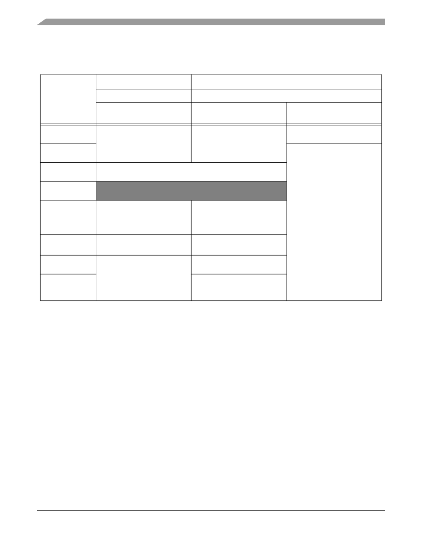
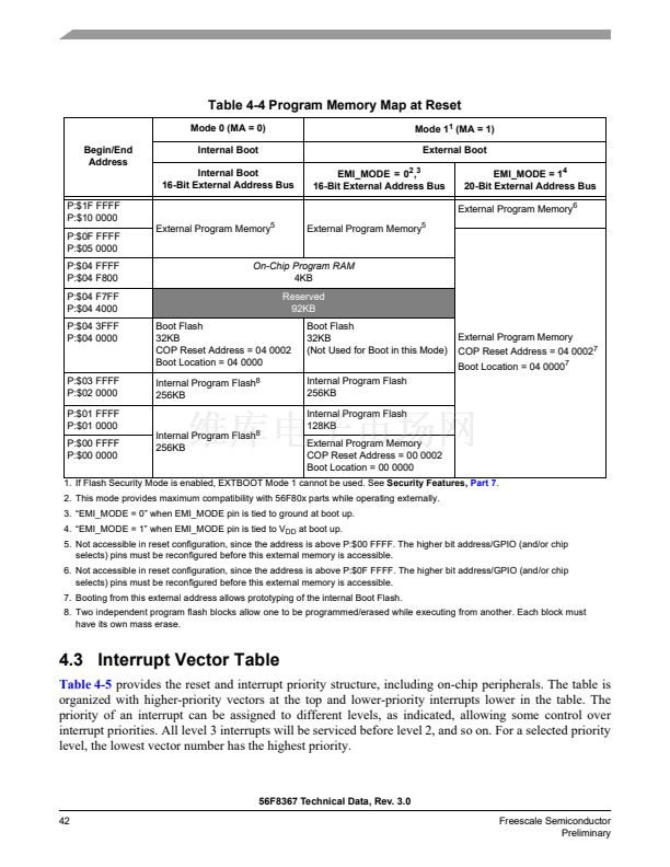
Table 4-4 Program Memory Map at Reset
Mode 0 (MA = 0)
Begin/End
Address
Internal Boot
Internal Boot
16-Bit External Address Bus
P:$1F FFFF
P:$10 0000
P:$0F FFFF
P:$05 0000
P:$04 FFFF
P:$04 F800
P:$04 F7FF
P:$04 4000
P:$04 3FFF
P:$04 0000
Mode 1
1
(MA = 1)
External Boot
EMI_MODE = 0
2
,
3
16-Bit External Address Bus
EMI_MODE = 1
4
20-Bit External Address Bus
External Program Memory
6
External Program Memory
5
External Program Memory
5
On-Chip Program RAM
4KB
Reserved
92KB
Boot Flash
32KB
COP Reset Address = 04 0002
Boot Location = 04 0000
Internal Program Flash
8
256KB
Boot Flash
32KB
(Not Used for Boot in this Mode)
Internal Program Flash
256KB
Internal Program Flash
128KB
External Program Memory
COP Reset Address = 00 0002
Boot Location = 00 0000
External Program Memory
COP Reset Address = 04 0002
7
Boot Location = 04 0000
7
P:$03 FFFF
P:$02 0000
P:$01 FFFF
P:$01 0000
P:$00 FFFF
P:$00 0000
Internal Program Flash
8
256KB
1. If Flash Security Mode is enabled, EXTBOOT Mode 1 cannot be used. See
Security Features,
Part 7.
2. This mode provides maximum compatibility with 56F80x parts while operating externally.
3. 鈥淓MI_MODE = 0鈥?when EMI_MODE pin is tied to ground at boot up.
4. 鈥淓MI_MODE = 1鈥?when EMI_MODE pin is tied to V
DD
at boot up.
5. Not accessible in reset configuration, since the address is above P:$00 FFFF. The higher bit address/GPIO (and/or chip
selects) pins must be reconfigured before this external memory is accessible.
6. Not accessible in reset configuration, since the address is above P:$0F FFFF. The higher bit address/GPIO (and/or chip
selects) pins must be reconfigured before this external memory is accessible.
7. Booting from this external address allows prototyping of the internal Boot Flash.
8. Two independent program flash blocks allow one to be programmed/erased while executing from another. Each block must
have its own mass erase.
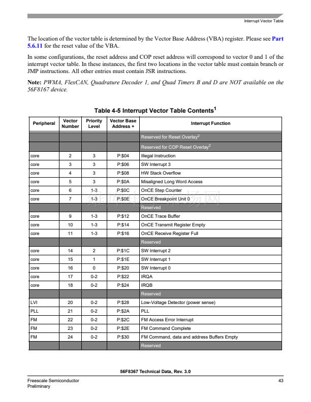
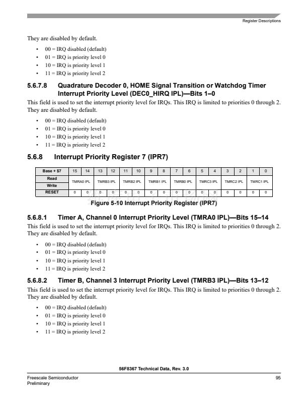
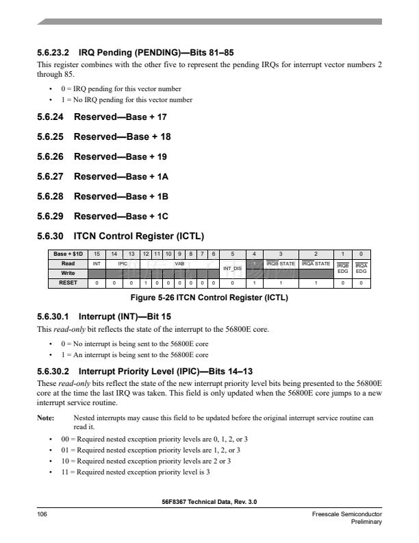
4.3 Interrupt Vector Table
Table 4-5
provides the reset and interrupt priority structure, including on-chip peripherals. The table is
organized with higher-priority vectors at the top and lower-priority interrupts lower in the table. The
priority of an interrupt can be assigned to different levels, as indicated, allowing some control over
interrupt priorities. All level 3 interrupts will be serviced before level 2, and so on. For a selected priority
level, the lowest vector number has the highest priority.
56F8367 Technical Data, Rev. 3.0
42
Freescale Semiconductor
Preliminary


 1
1
 2
2
 3
3
 4
4
 5
5
 6
6
 7
7
 8
8
 9
9
 10
10
 11
11
 12
12
 13
13
 14
14
 15
15
 16
16
 17
17
 18
18
 19
19
 20
20
 21
21
 22
22
 23
23
 24
24
 25
25
 26
26
 27
27
 28
28
 29
29
 30
30
 31
31
 32
32
 33
33
 34
34
 35
35
 36
36
 37
37
 38
38
 39
39
 40
40
 41
41
 42
42
 43
43
 44
44
 45
45
 46
46
 47
47
 48
48
 49
49
 50
50
 51
51
 52
52
 53
53
 54
54
 55
55
 56
56
 57
57
 58
58
 59
59
 60
60
 61
61
 62
62
 63
63
 64
64
 65
65
 66
66
 67
67
 68
68
 69
69
 70
70
 71
71
 72
72
 73
73
 74
74
 75
75
 76
76
 77
77
 78
78
 79
79
 80
80
 81
81
 82
82
 83
83
 84
84
 85
85
 86
86
 87
87
 88
88
 89
89
 90
90
 91
91
 92
92
 93
93
 94
94
 95
95
 96
96
 97
97
 98
98
 99
99
 100
100
 101
101
 102
102
 103
103
 104
104
 105
105
 106
106
 107
107
 108
108
 109
109
 110
110
 111
111
 112
112
 113
113
 114
114
 115
115
 116
116
 117
117
 118
118
 119
119
 120
120
 121
121
 122
122
 123
123
 124
124
 125
125
 126
126
 127
127
 128
128
 129
129
 130
130
 131
131
 132
132
 133
133
 134
134
 135
135
 136
136
 137
137
 138
138
 139
139
 140
140
 141
141
 142
142
 143
143
 144
144
 145
145
 146
146
 147
147
 148
148
 149
149
 150
150
 151
151
 152
152
 153
153
 154
154
 155
155
 156
156
 157
157
 158
158
 159
159
 160
160
 161
161
 162
162
 163
163
 164
164
 165
165
 166
166
 167
167
 168
168
 169
169
 170
170
 171
171
 172
172
 173
173
 174
174
 175
175
 176
176
 177
177
 178
178
 179
179
 180
180
