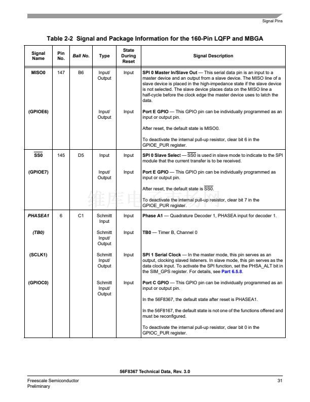
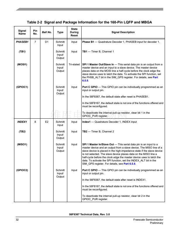
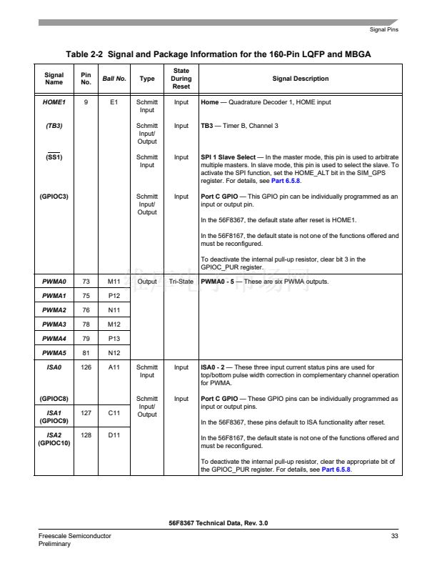
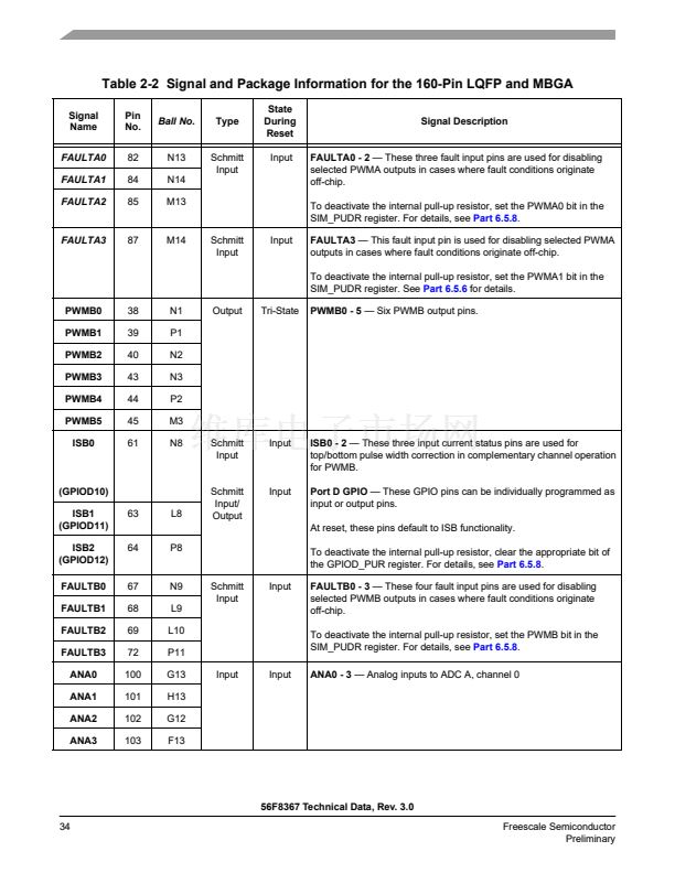
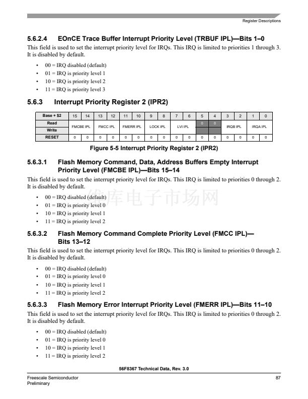
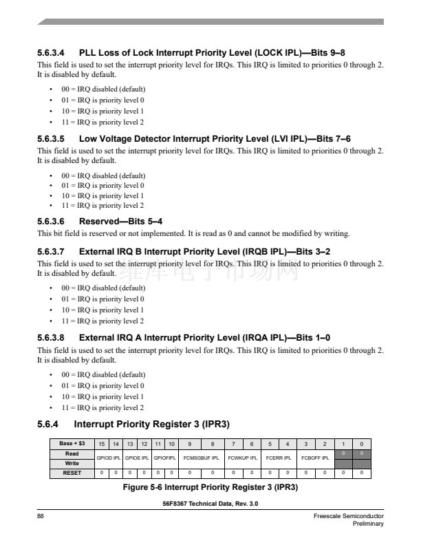
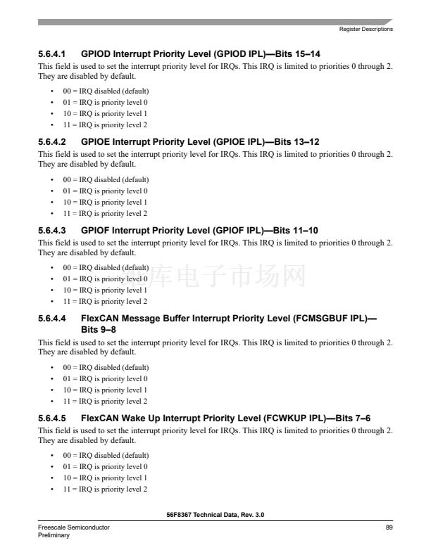
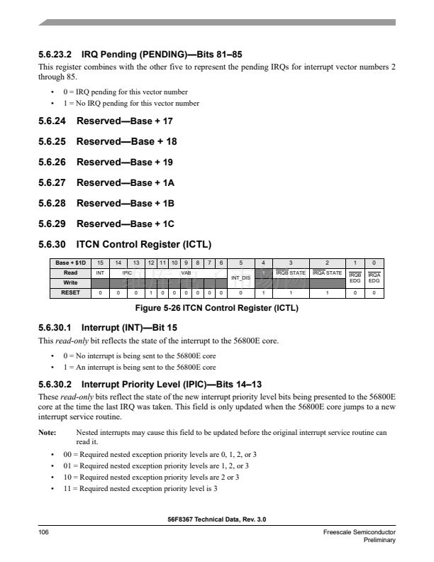
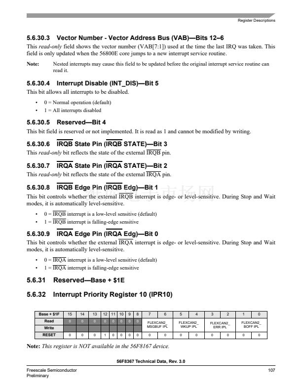
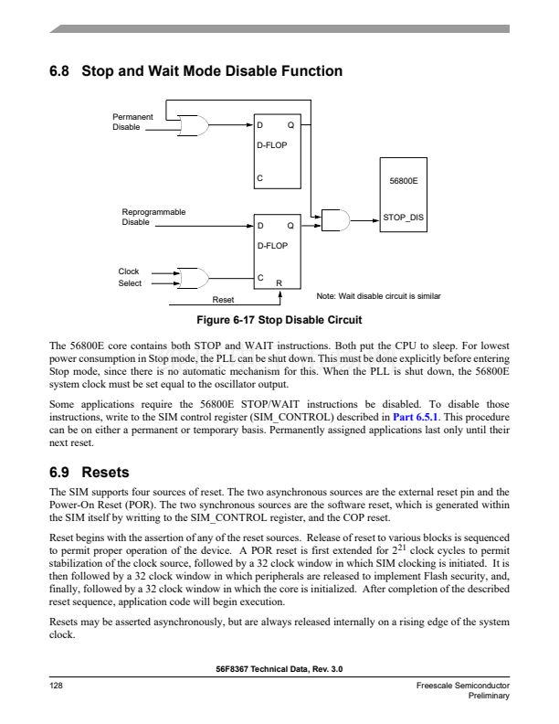
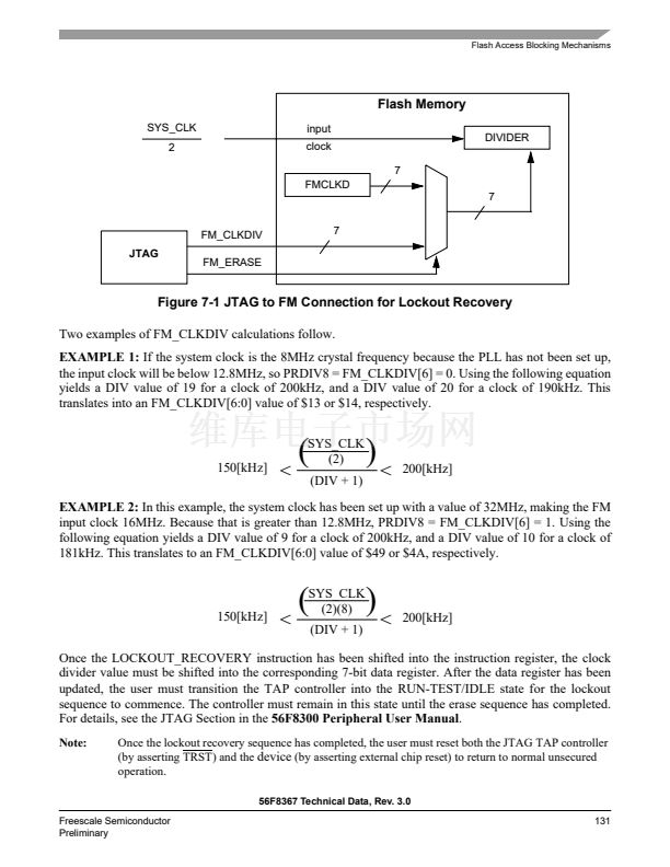
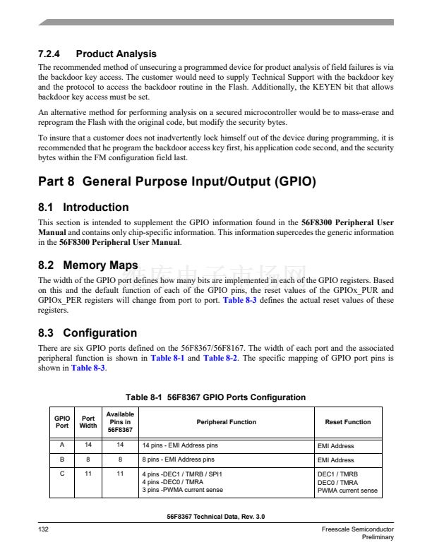
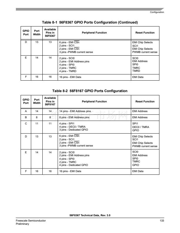
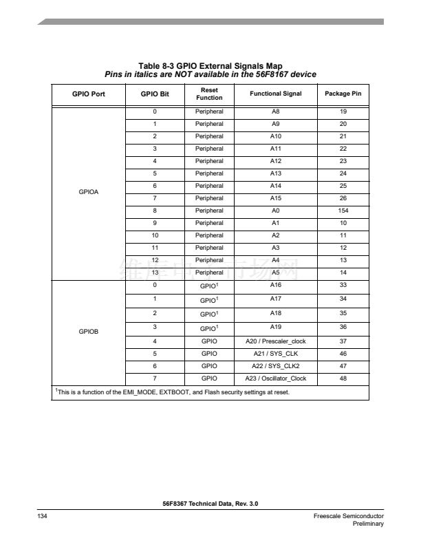
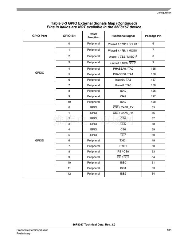
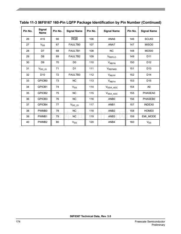
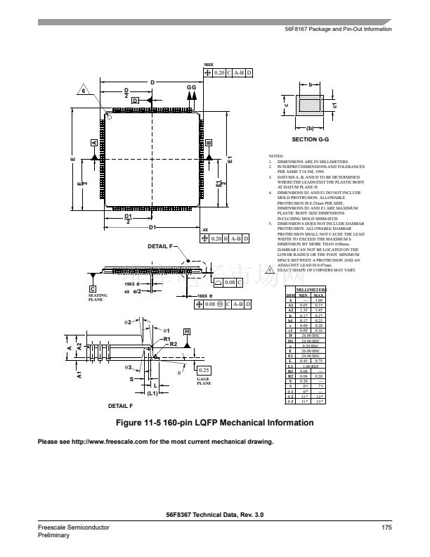
鈥?/div>
Programmable priority levels for each IRQ
Two programmable Fast Interrupts
Notification to SIM module to restart clocks out of Wait and Stop modes
Drives initial address on the address bus after reset
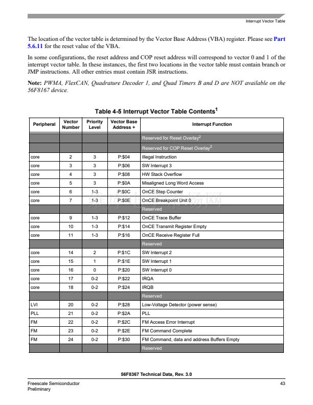
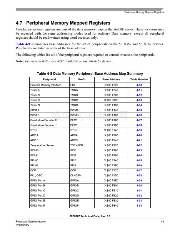
For further information, see
Table 4-5,
Interrupt Vector Table Contents.
5.3 Functional Description
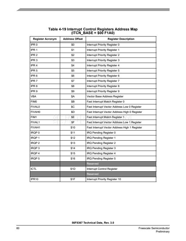
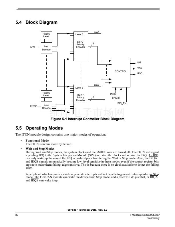
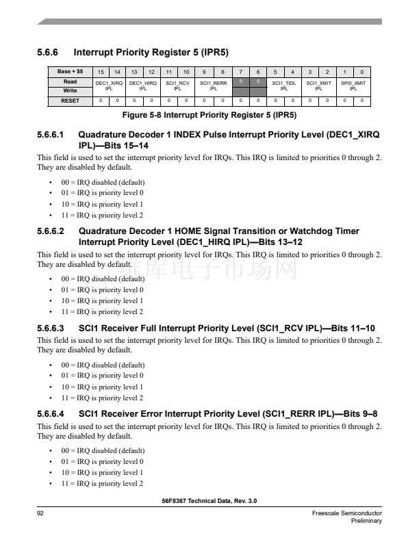
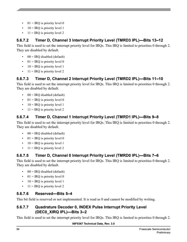
The Interrupt Controller is a slave on the IPBus. It contains registers allowing each of the 86 interrupt
sources to be set to one of four priority levels, excluding certain interrupts of fixed priority. Next, all of
the interrupt requests of a given level are priority encoded to determine the lowest numerical value of the
active interrupt requests for that level. Within a given priority level, 0 is the highest priority, while number
85 is the lowest.
5.3.1
Normal Interrupt Handling
Once the ITCN has determined that an interrupt is to be serviced and which interrupt has the highest
priority, an interrupt vector address is generated. Normal interrupt handling concatenates the VBA and the
vector number to determine the vector address. In this way, an offset is generated into the vector table for
each interrupt.
5.3.2
Interrupt Nesting
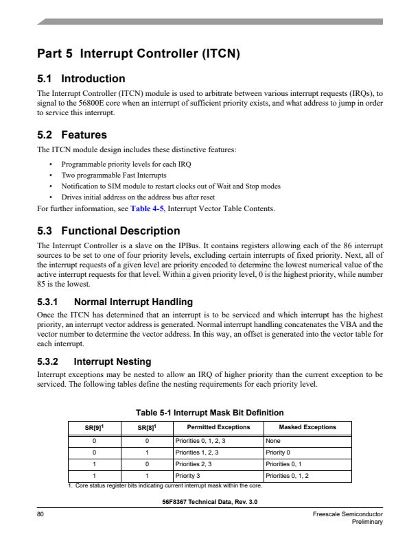
Interrupt exceptions may be nested to allow an IRQ of higher priority than the current exception to be
serviced. The following tables define the nesting requirements for each priority level.
Table 5-1 Interrupt Mask Bit Definition
SR[9]
1
0
0
1
1
SR[8]
1
0
1
0
1
Permitted Exceptions
Priorities 0, 1, 2, 3
Priorities 1, 2, 3
Priorities 2, 3
Priority 3
Masked Exceptions
None
Priority 0
Priorities 0, 1
Priorities 0, 1, 2
1. Core status register bits indicating current interrupt mask within the core.
56F8367 Technical Data, Rev. 3.0
80
Freescale Semiconductor
Preliminary


 1
1
 2
2
 3
3
 4
4
 5
5
 6
6
 7
7
 8
8
 9
9
 10
10
 11
11
 12
12
 13
13
 14
14
 15
15
 16
16
 17
17
 18
18
 19
19
 20
20
 21
21
 22
22
 23
23
 24
24
 25
25
 26
26
 27
27
 28
28
 29
29
 30
30
 31
31
 32
32
 33
33
 34
34
 35
35
 36
36
 37
37
 38
38
 39
39
 40
40
 41
41
 42
42
 43
43
 44
44
 45
45
 46
46
 47
47
 48
48
 49
49
 50
50
 51
51
 52
52
 53
53
 54
54
 55
55
 56
56
 57
57
 58
58
 59
59
 60
60
 61
61
 62
62
 63
63
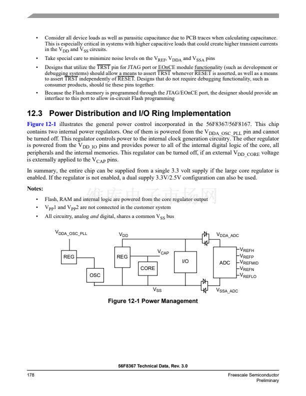
 64
64
 65
65
 66
66
 67
67
 68
68
 69
69
 70
70
 71
71
 72
72
 73
73
 74
74
 75
75
 76
76
 77
77
 78
78
 79
79
 80
80
 81
81
 82
82
 83
83
 84
84
 85
85
 86
86
 87
87
 88
88
 89
89
 90
90
 91
91
 92
92
 93
93
 94
94
 95
95
 96
96
 97
97
 98
98
 99
99
 100
100
 101
101
 102
102
 103
103
 104
104
 105
105
 106
106
 107
107
 108
108
 109
109
 110
110
 111
111
 112
112
 113
113
 114
114
 115
115
 116
116
 117
117
 118
118
 119
119
 120
120
 121
121
 122
122
 123
123
 124
124
 125
125
 126
126
 127
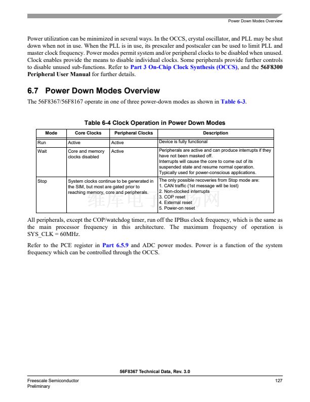
127
 128
128
 129
129
 130
130
 131
131
 132
132
 133
133
 134
134
 135
135
 136
136
 137
137
 138
138
 139
139
 140
140
 141
141
 142
142
 143
143
 144
144
 145
145
 146
146
 147
147
 148
148
 149
149
 150
150
 151
151
 152
152
 153
153
 154
154
 155
155
 156
156
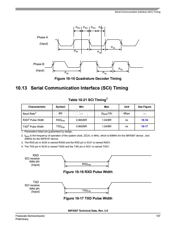 157
157
 158
158
 159
159
 160
160
 161
161
 162
162
 163
163
 164
164
 165
165
 166
166
 167
167
 168
168
 169
169
 170
170
 171
171
 172
172
 173
173
 174
174
 175
175
 176
176
 177
177
 178
178
 179
179
 180
180
