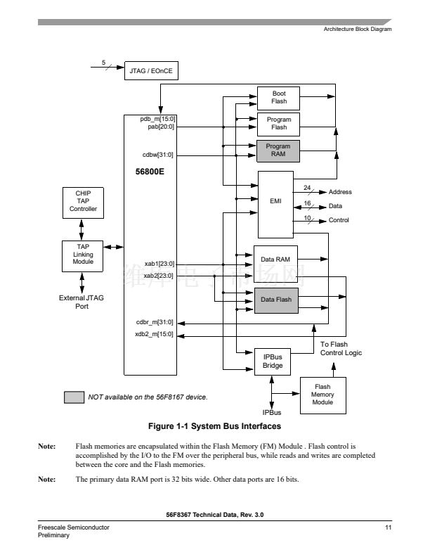
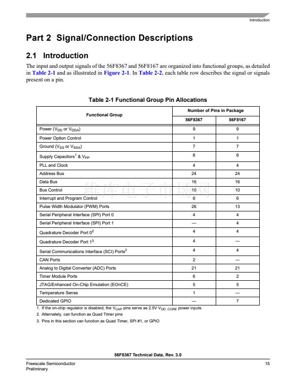
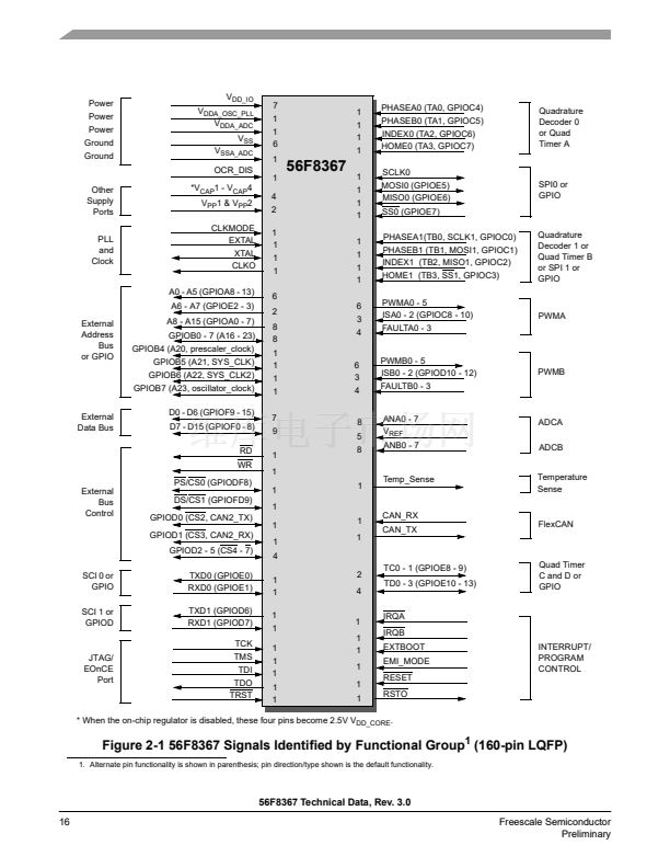
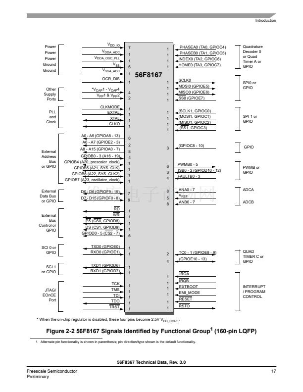
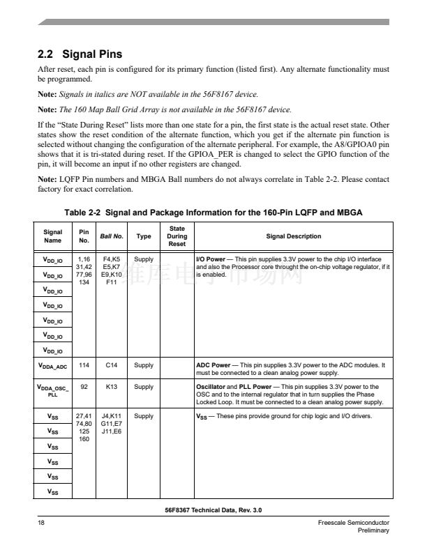
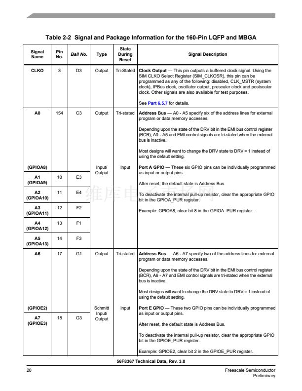
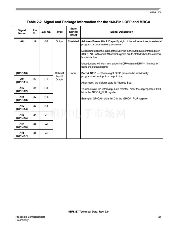
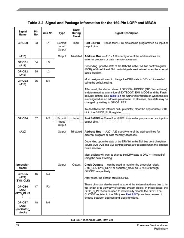
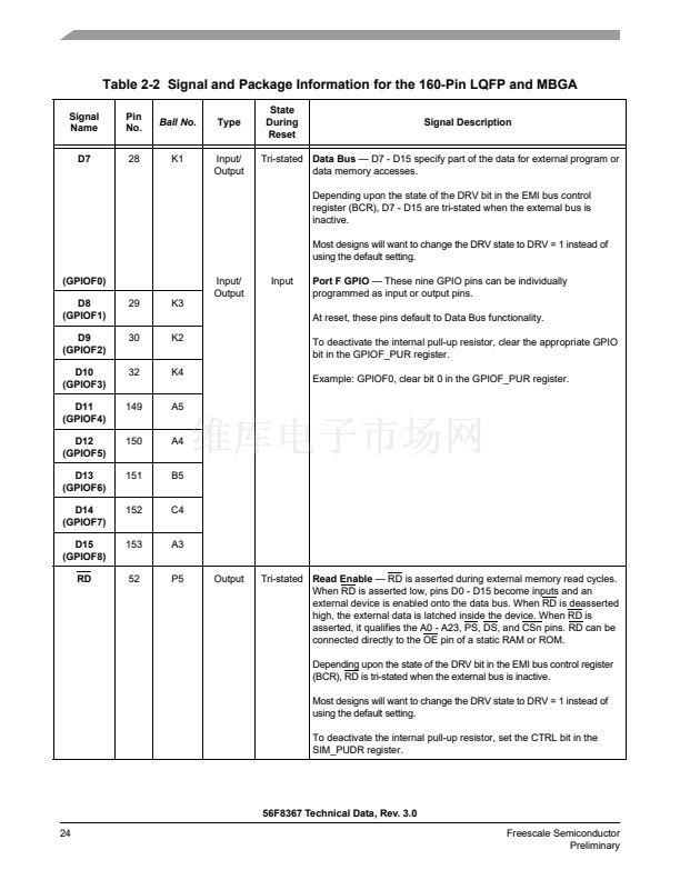
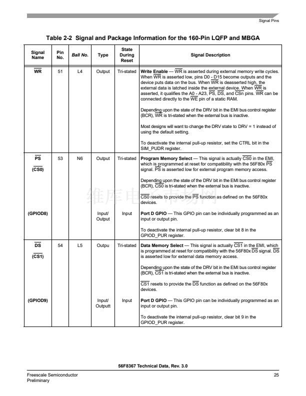
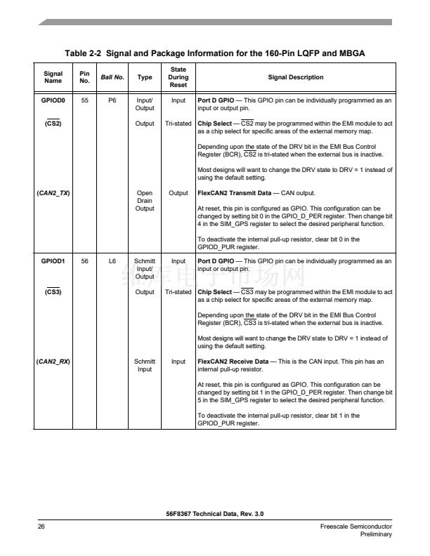
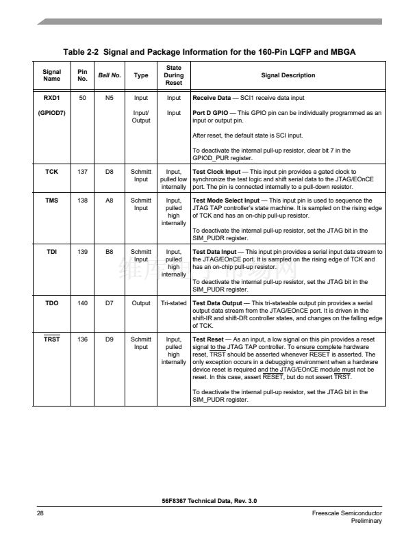
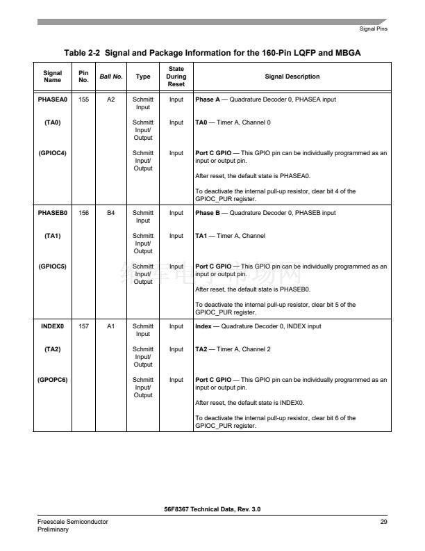
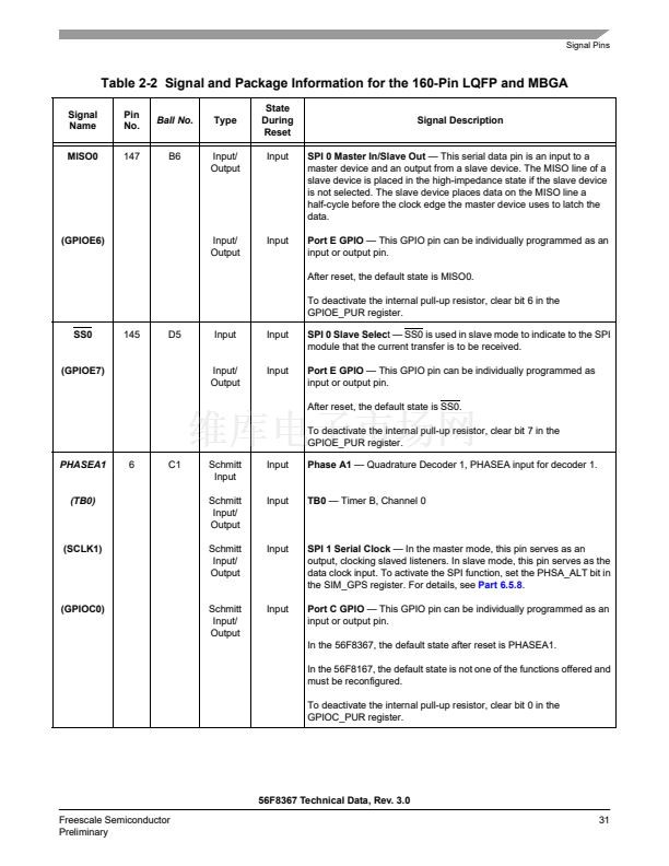
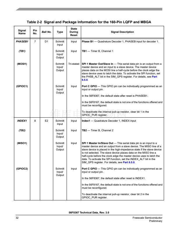
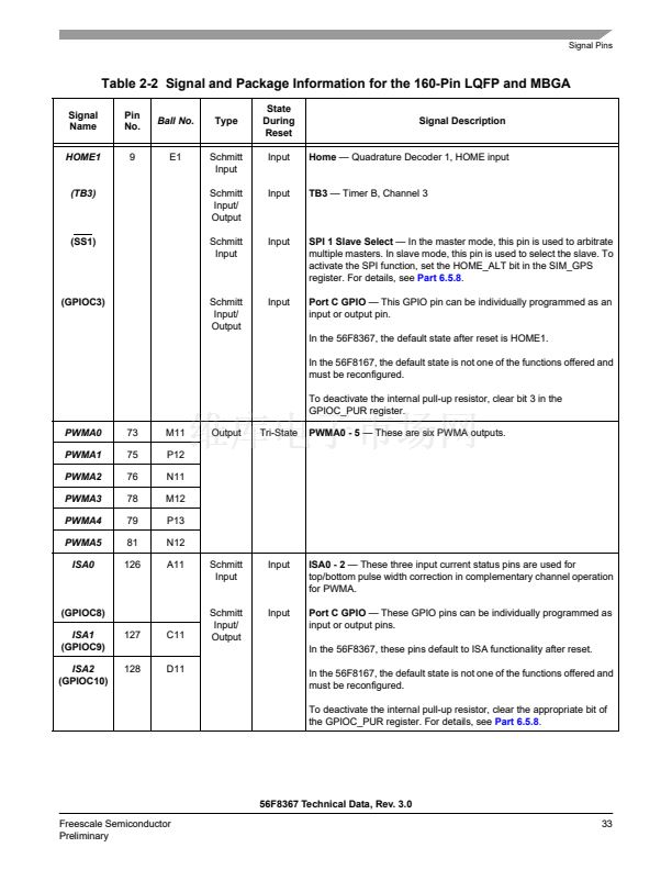
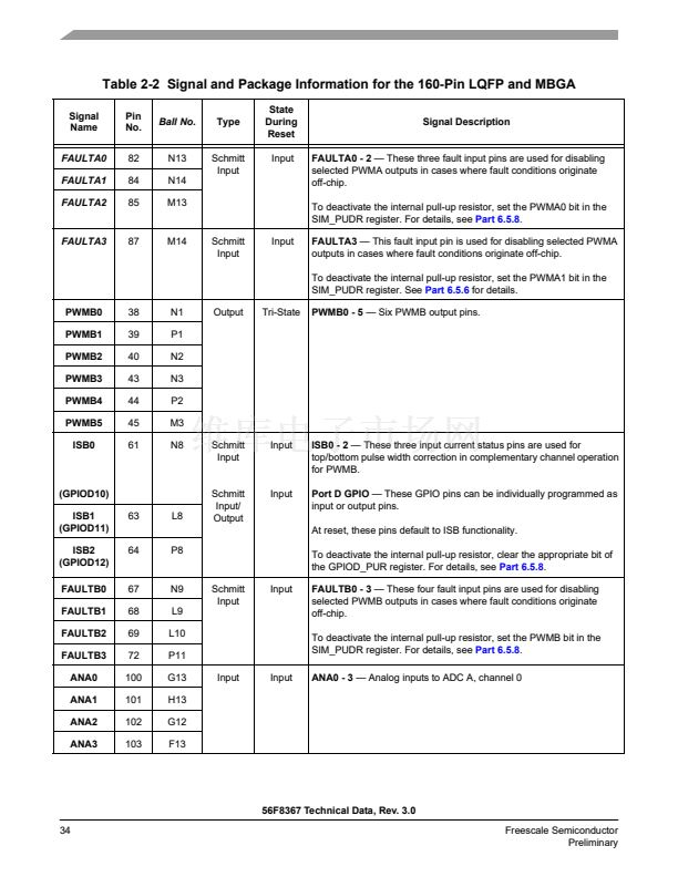
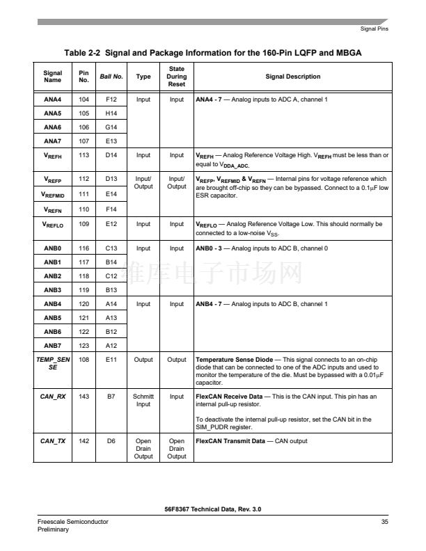
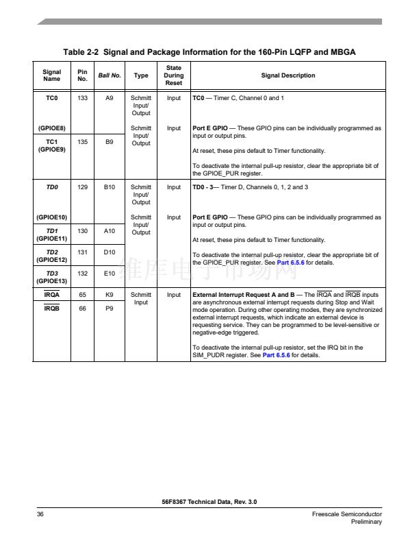
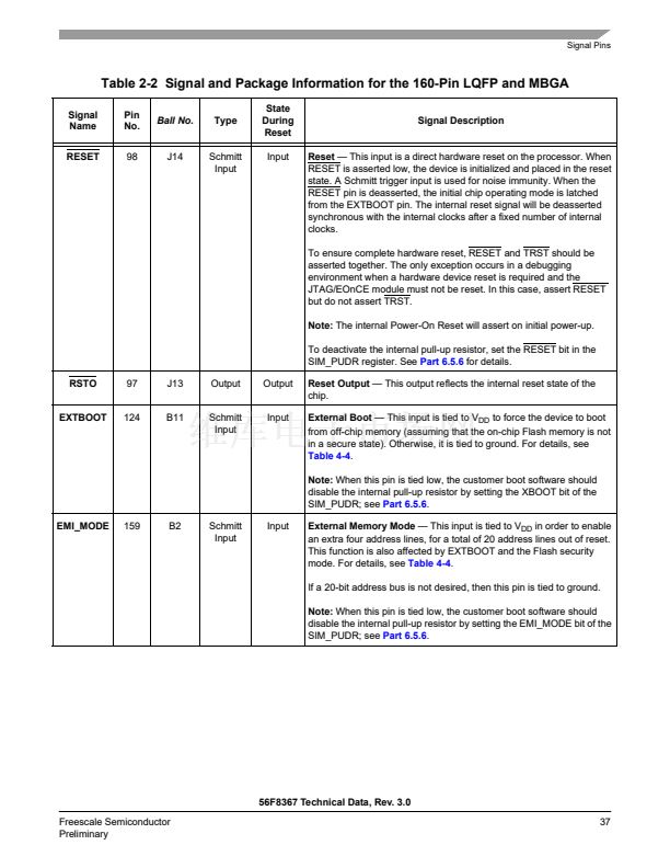
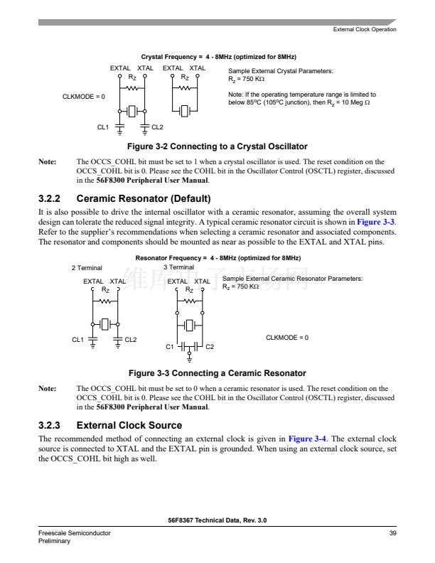
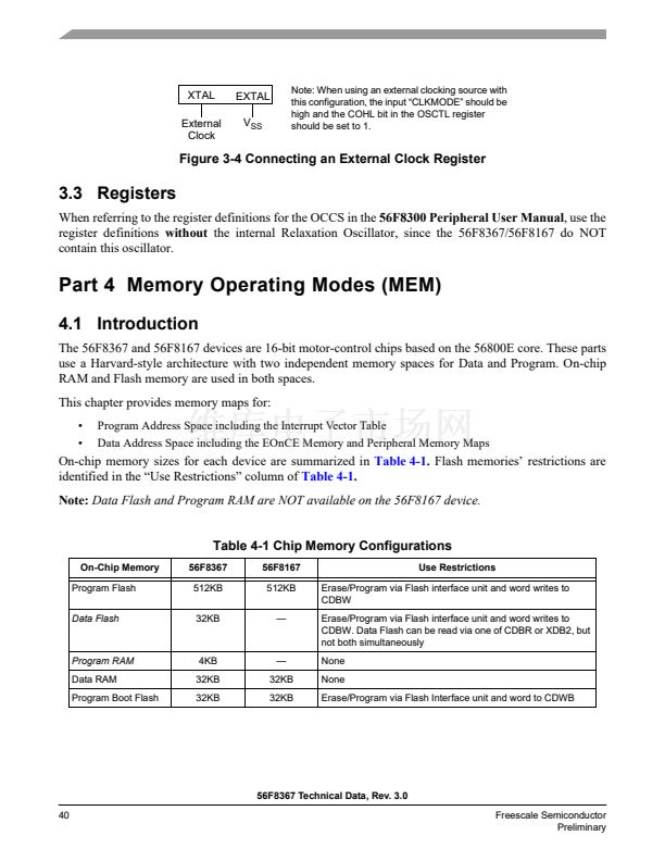
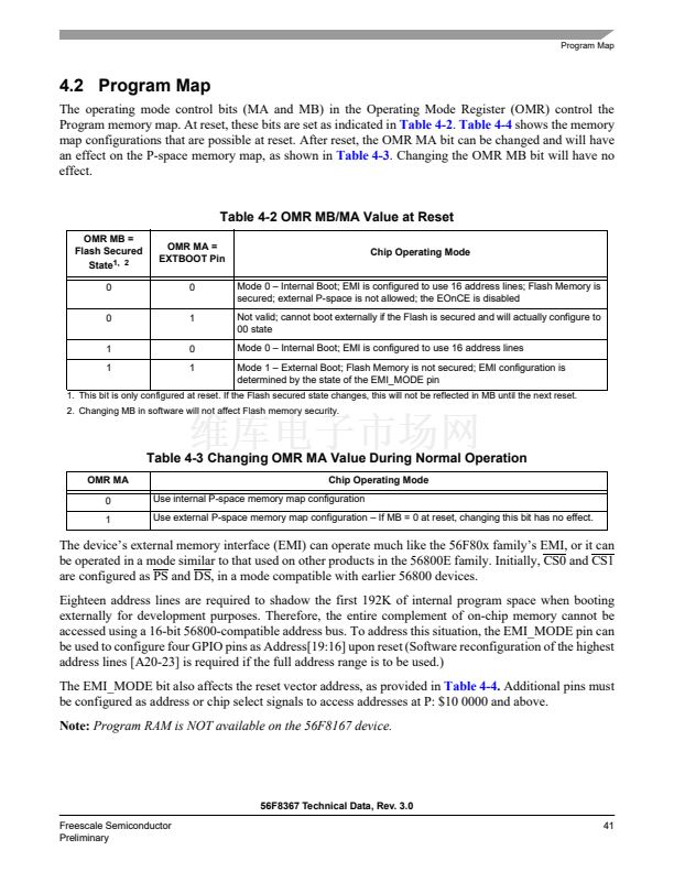
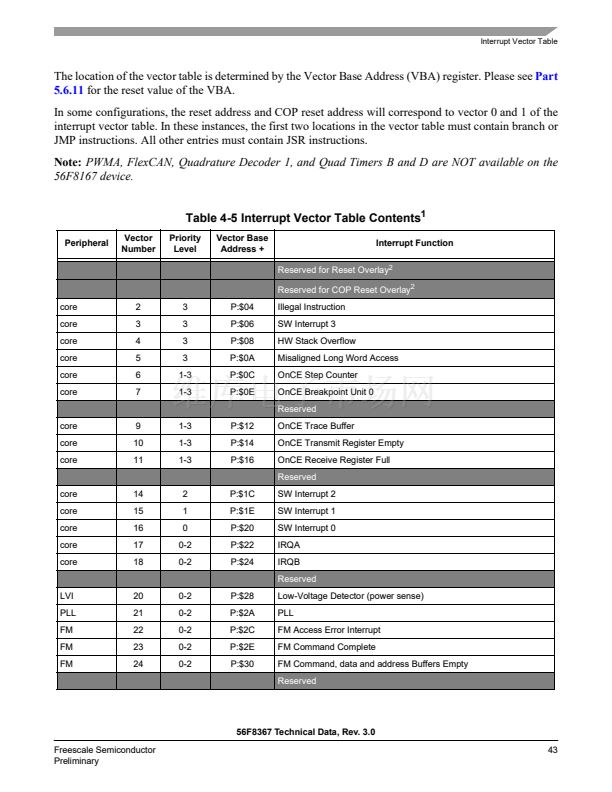
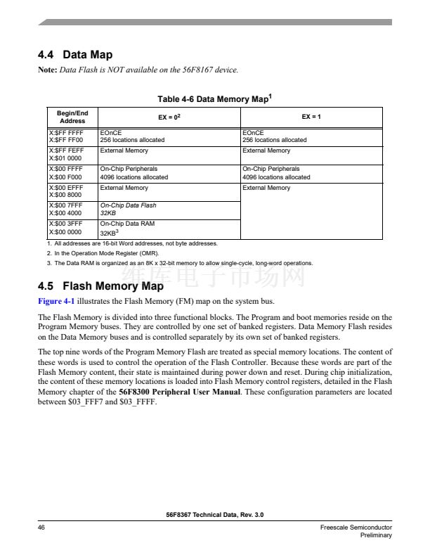
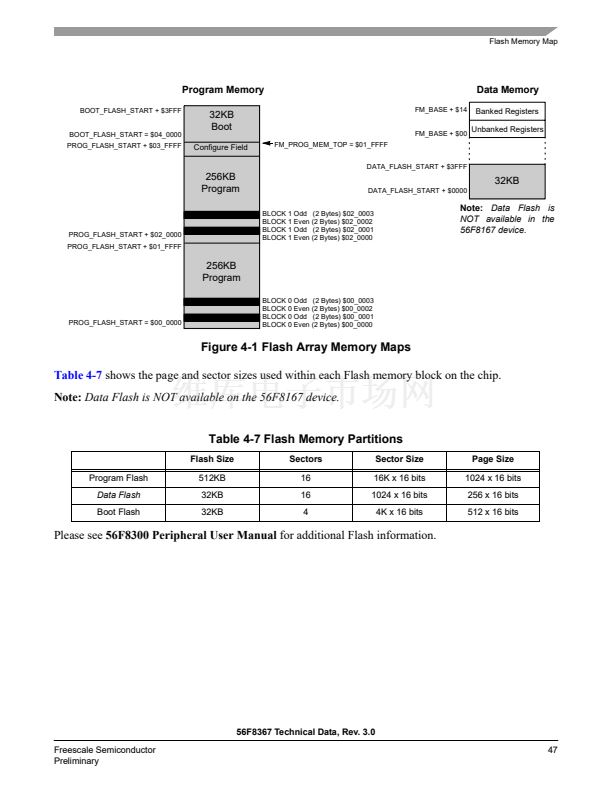
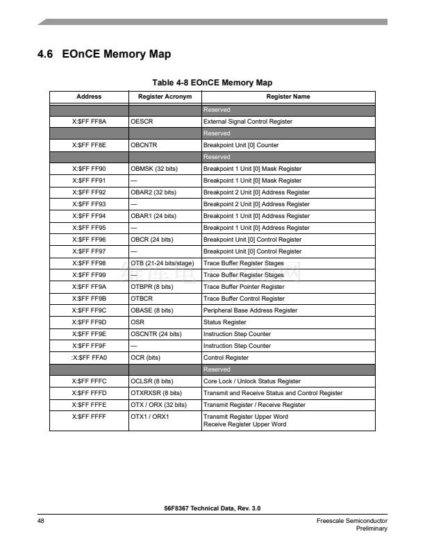
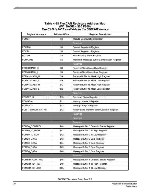
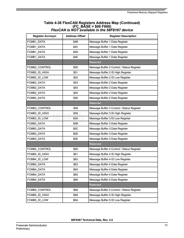
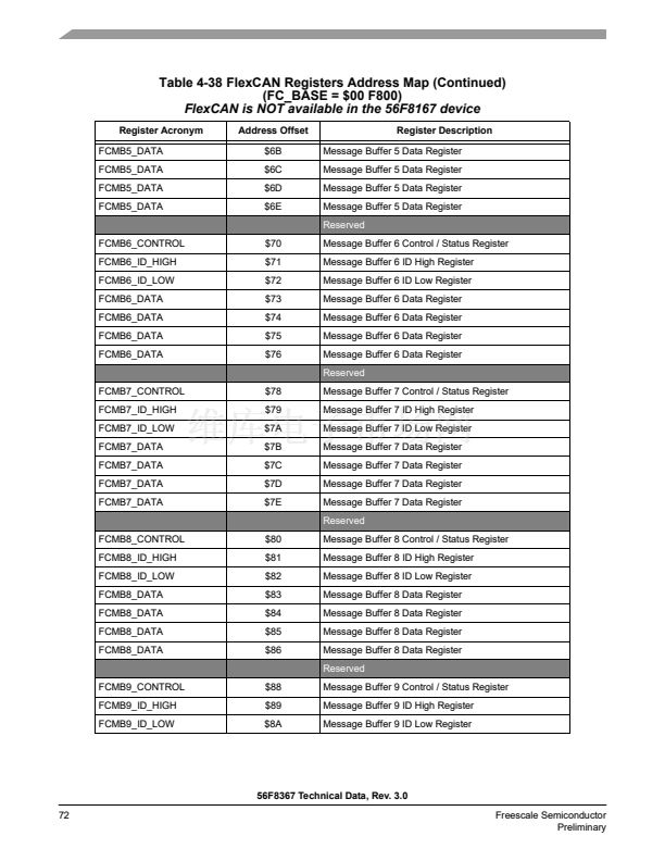
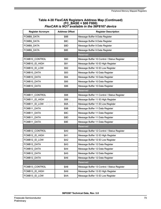
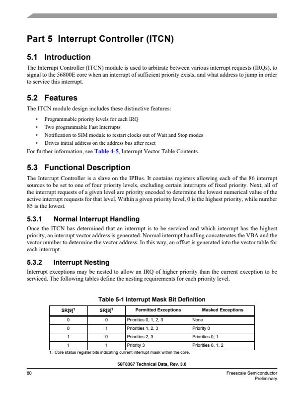
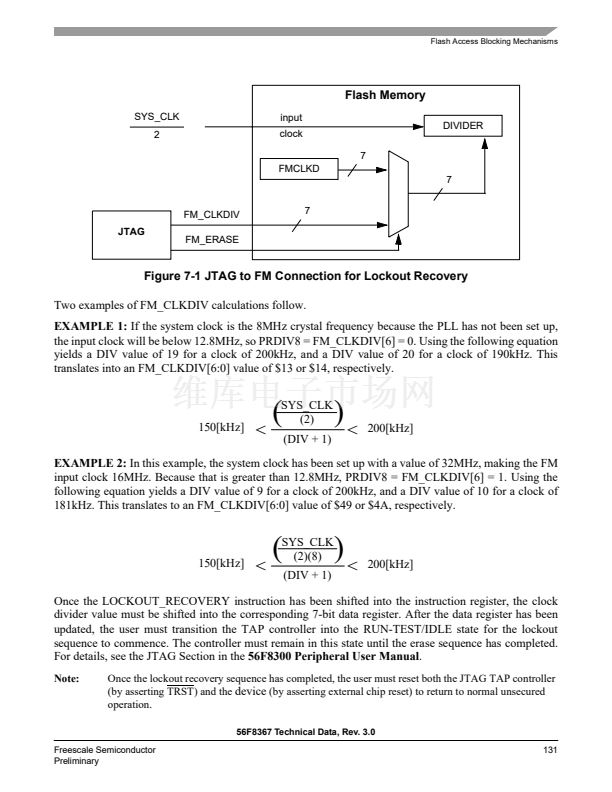
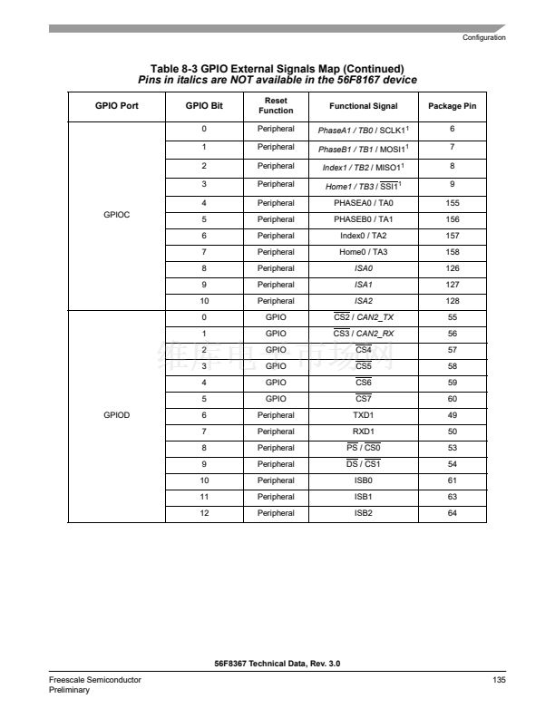
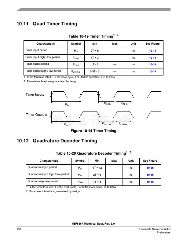
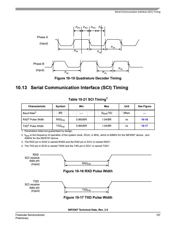
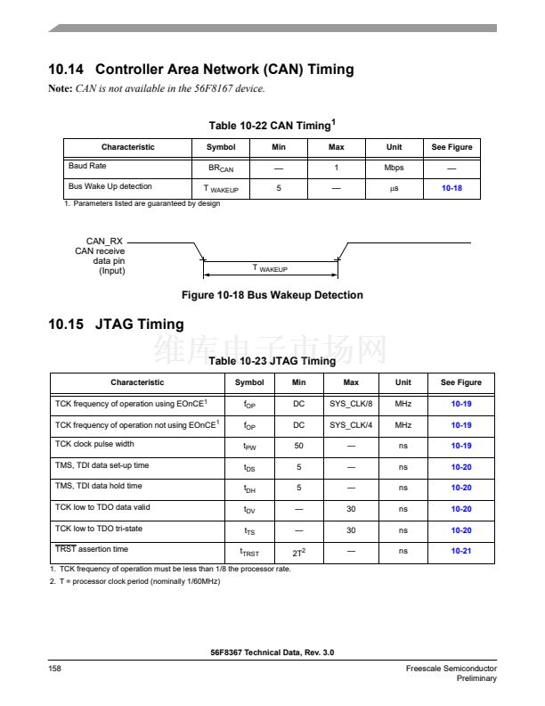
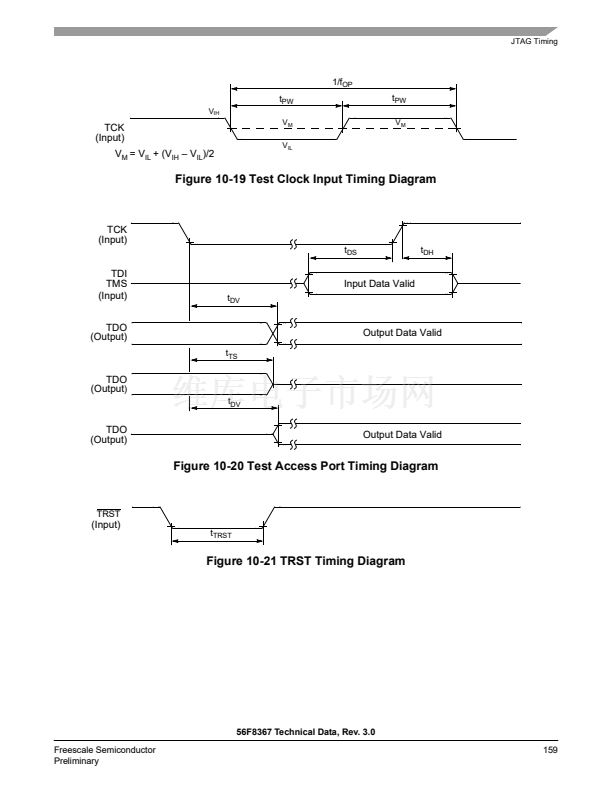
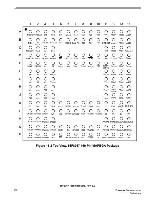
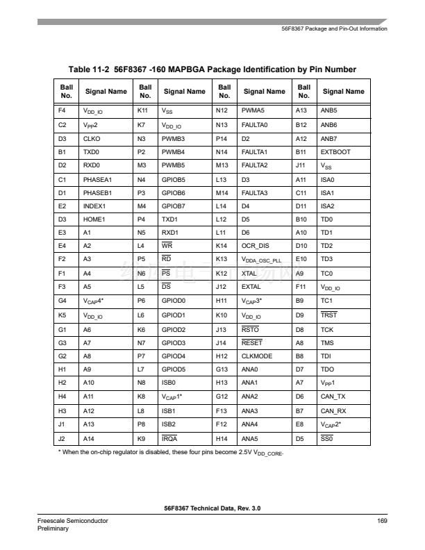
Signal Pins
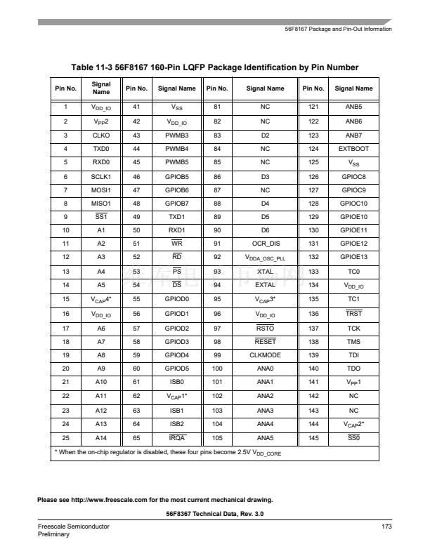
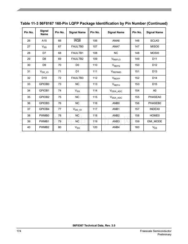
Table 2-2 Signal and Package Information for the 160-Pin LQFP and MBGA
Signal
Name
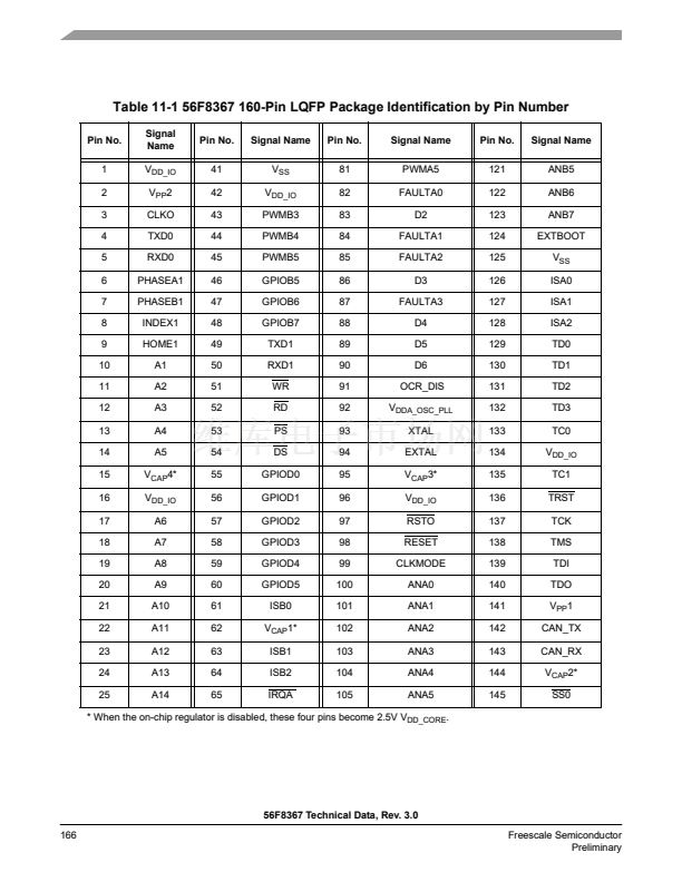
RESET
Pin
No.
98
Ball No.
Type
State
During
Reset
Input
Signal Description
J14
Schmitt
Input
Reset
鈥?This input is a direct hardware reset on the processor. When
RESET is asserted low, the device is initialized and placed in the reset
state. A Schmitt trigger input is used for noise immunity. When the
RESET pin is deasserted, the initial chip operating mode is latched
from the EXTBOOT pin. The internal reset signal will be deasserted
synchronous with the internal clocks after a fixed number of internal
clocks.
To ensure complete hardware reset, RESET and TRST should be
asserted together. The only exception occurs in a debugging
environment when a hardware device reset is required and the
JTAG/EOnCE module must not be reset. In this case, assert RESET
but do not assert TRST.
Note:
The internal Power-On Reset will assert on initial power-up.
To deactivate the internal pull-up resistor, set the RESET bit in the
SIM_PUDR register. See
Part 6.5.6
for details.
RSTO
97
J13
Output
Output
Reset Output
鈥?This output reflects the internal reset state of the
chip.
External Boot
鈥?This input is tied to V
DD
to force the device to boot
from off-chip memory (assuming that the on-chip Flash memory is not
in a secure state). Otherwise, it is tied to ground. For details, see
Table 4-4.
Note:
When this pin is tied low, the customer boot software should
disable the internal pull-up resistor by setting the XBOOT bit of the
SIM_PUDR; see
Part 6.5.6.
EXTBOOT
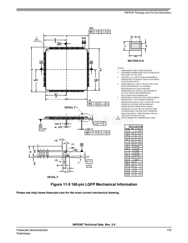
124
B11
Schmitt
Input
Input
EMI_MODE
159
B2
Schmitt
Input
Input
External Memory Mode
鈥?This input is tied to V
DD
in order to enable
an extra four address lines, for a total of 20 address lines out of reset.
This function is also affected by EXTBOOT and the Flash security
mode. For details, see
Table 4-4.
If a 20-bit address bus is not desired, then this pin is tied to ground.
Note:
When this pin is tied low, the customer boot software should
disable the internal pull-up resistor by setting the EMI_MODE bit of the
SIM_PUDR; see
Part 6.5.6.
56F8367 Technical Data, Rev. 3.0
Freescale Semiconductor
Preliminary
37


 1
1
 2
2
 3
3
 4
4
 5
5
 6
6
 7
7
 8
8
 9
9
 10
10
 11
11
 12
12
 13
13
 14
14
 15
15
 16
16
 17
17
 18
18
 19
19
 20
20
 21
21
 22
22
 23
23
 24
24
 25
25
 26
26
 27
27
 28
28
 29
29
 30
30
 31
31
 32
32
 33
33
 34
34
 35
35
 36
36
 37
37
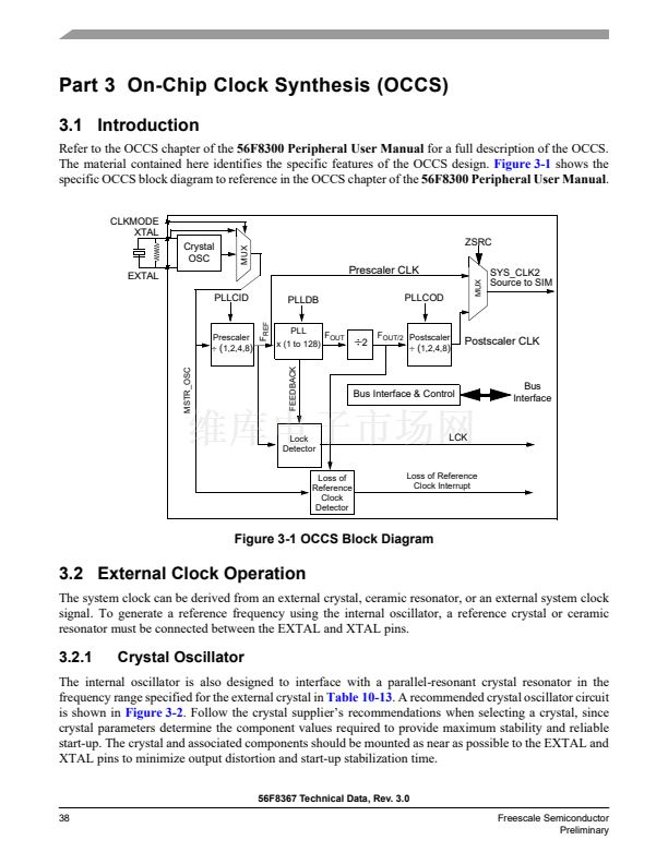 38
38
 39
39
 40
40
 41
41
 42
42
 43
43
 44
44
 45
45
 46
46
 47
47
 48
48
 49
49
 50
50
 51
51
 52
52
 53
53
 54
54
 55
55
 56
56
 57
57
 58
58
 59
59
 60
60
 61
61
 62
62
 63
63
 64
64
 65
65
 66
66
 67
67
 68
68
 69
69
 70
70
 71
71
 72
72
 73
73
 74
74
 75
75
 76
76
 77
77
 78
78
 79
79
 80
80
 81
81
 82
82
 83
83
 84
84
 85
85
 86
86
 87
87
 88
88
 89
89
 90
90
 91
91
 92
92
 93
93
 94
94
 95
95
 96
96
 97
97
 98
98
 99
99
 100
100
 101
101
 102
102
 103
103
 104
104
 105
105
 106
106
 107
107
 108
108
 109
109
 110
110
 111
111
 112
112
 113
113
 114
114
 115
115
 116
116
 117
117
 118
118
 119
119
 120
120
 121
121
 122
122
 123
123
 124
124
 125
125
 126
126
 127
127
 128
128
 129
129
 130
130
 131
131
 132
132
 133
133
 134
134
 135
135
 136
136
 137
137
 138
138
 139
139
 140
140
 141
141
 142
142
 143
143
 144
144
 145
145
 146
146
 147
147
 148
148
 149
149
 150
150
 151
151
 152
152
 153
153
 154
154
 155
155
 156
156
 157
157
 158
158
 159
159
 160
160
 161
161
 162
162
 163
163
 164
164
 165
165
 166
166
 167
167
 168
168
 169
169
 170
170
 171
171
 172
172
 173
173
 174
174
 175
175
 176
176
 177
177
 178
178
 179
179
 180
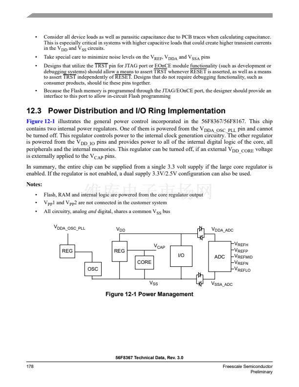
180
