ST24/25C02, ST24C02R, ST24/25W02
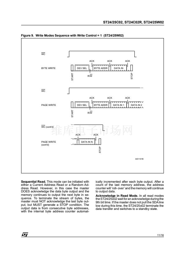
Figure 9. Write Modes Sequence with Write Control = 1 (ST24/25W02)
WC
ACK
BYTE WRITE
DEV SEL
ACK
DATA IN
ACK
BYTE ADDR
R/W
WC
ACK
PAGE WRITE
DEV SEL
ACK
DATA IN 1
ACK
DATA IN 2
START
BYTE ADDR
R/W
WC (cont'd)
ACK
PAGE WRITE
(cont'd)
DATA IN N
ACK
START
STOP
STOP
AI01101B
Sequential Read.
This mode can be initiated with
either a Current Address Read or a Random Ad-
dress Read. However, in this case the master
DOES acknowledge the data byte output and the
memory continues to output the next byte in se-
quence. To terminate the stream of bytes, the
master must NOT acknowledge the last byte out-
put, but MUST generate a STOP condition. The
output data is from consecutive byte addresses,
with the internal byte address counter automat-
ically incremented after each byte output. After a
count of the last memory address, the address
counter will 鈥檙oll- over鈥?and the memory will continue
to output data.
Acknowledge in Read Mode.
In all read modes
the ST24/25x02 wait for an acknowledge during the
9th bit time. If the master does not pull the SDA line
low during this time, the ST24/25x02 terminate the
data transfer and switches to a standby state.
11/16


 1
1
 2
2
 3
3
 4
4
 5
5
 6
6
 7
7
 8
8
 9
9
 10
10
 11
11
 12
12
 13
13
 14
14
 15
15
 16
16
