鈫?/div>
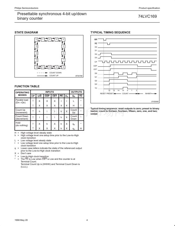
U/D
X
X
h
l
X
X
CEP
X
X
l
l
h
X
CET
X
X
l
l
X
X
PE
l
X
h
h
h
h
D
n
l
X
X
X
X
X
OUTPUTS
Q
n
L
H
Count
Up
Count
Down
q
n
q
n
TC
*
*
*
*
*
H
TC
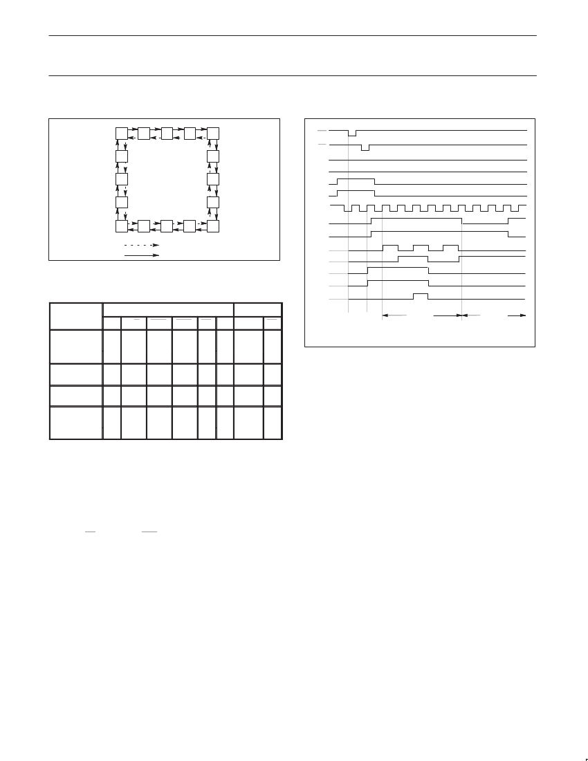
12
13
14
15
0
1
2
INHIBIT
RESET PRESET
COUNT
SY00069
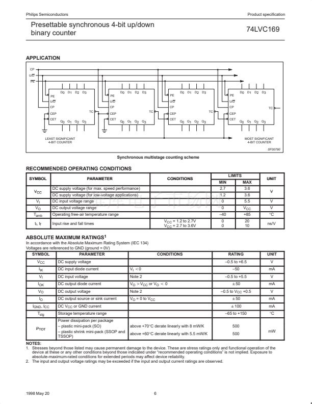
Typical timing sequence: reset outputs to zero; preset to binary
twelve; count to thirteen, fourteen, fifteen, zero, one, and two;
inhibit
H = High voltage level steady state
h = High voltage level one setup time prior to the Low-to-High
clock transition
L = Low voltage level steady state
l = Low voltage level one setup time prior to the Low-to-High
clock transition
q = Lower case letters indicate the state of the referenced output
prior to the Low-to-High clock transition
X = Don鈥檛 care
鈫?/div>
= Low-to-High clock transition
* = The TC is Low when CET is Low and the counter is at
Terminal Count.
Terminal Count Up is (HHHH) and Terminal Count Down is
(LLLL).
1998 May 20
4


 1
1
 2
2
 3
3
 4
4
 5
5
 6
6
 7
7
 8
8
 9
9
 10
10
 11
11
 12
12
 13
13
 14
14
