ADM4850鈥揂DM4857
HIGH RECEIVER INPUT IMPEDANCE
The input impedance of the ADM485x receivers is 96 k鈩?
which is 8 times higher than the standard RS-485 unit load of
12 k鈩? This 96 k鈩?impedance, enables a standard driver to
drive 32 unit loads or be connected to 256 ADM485x receivers.
An RS-485 bus, driven by a single standard driver, can be
connected to a combination of ADM485x and standard unit
load receivers, up to an equivalent of 32 standard unit loads.
FAIL-SAFE OPERATION
The ADM4850鈥揂DM4857 offer true fail-safe operation while
remaining fully compliant with the 卤200 mV EIA/TIA-485
standard. A logic-high receiver output is generated when the
receiver inputs are shorted together or open-circuit, or when
they are connected to a terminated transmission line with all
drivers disabled. This is done by setting the receiver threshold
between 鈭?0 mV and 鈭?00 mV. If the differential receiver input
voltage (A-B) is greater than or equal to 鈭?0 mV, RO is logic
high. If A-B is less than or equal to 鈭?00 mV, RO is logic low. In
the case of a terminated bus with all transmitters disabled, the
receiver鈥檚 differential input voltage is pulled to 0 V by the
ADM485x鈥檚 internal circuitry, which results in a logic high with
30 mV minimum noise margin.
THREE-STATE BUS CONNECTION
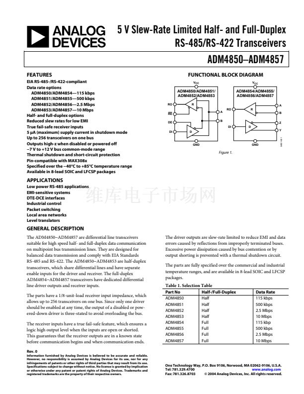
The half-duplex parts have a driver enable (DE) pin that enables
the driver outputs when taken high, or puts the driver outputs
into a high impedance state when taken low. Similarly, the half-
duplex devices have an active-low receiver enable (RE) pin.
Taking this pin low enables the receiver, while taking it high
puts the receiver outputs into a high impedance state. This
allows several driver outputs to be connected to an RS-485 bus.
Note that only one driver should be enabled at a time, while
many receivers can be enabled.
CURRENT LIMIT AND THERMAL SHUTDOWN
The ADM485x incorporates two protection mechanisms to
guard the drivers against short circuits, bus contention, or other
fault conditions. The first is a current-limiting output stage,
which protects the driver against short circuits over the entire
common-mode voltage range by limiting the output current to
approximately 70 mA. Under extreme fault conditions where
the current limit is not effective, a thermal shutdown circuit
puts the driver outputs into a high impedance state if the die
temperature exceeds 150掳C, and does not turn them back on
until the temperature falls to 130掳C.
SHUTDOWN MODE
The ADM4850鈥揂DM4853 have a low power shutdown mode,
which is enabled by taking RE high and DE low. If shutdown
mode is not used, the fact that DE is active high and RE is active
low offers a convenient way of switching the device between
transmit and receive by tying DE and RE together.
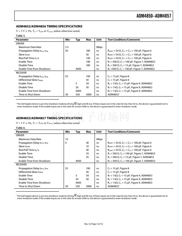
The devices are guaranteed not to enter shutdown mode if DE
and RE are driven in this way. If DE is low and RE is high for
less than 50 ns, the device does not enter shutdown mode. If DE
is low and RE is high for less than 3000 ns, the device is
guaranteed to enter shutdown mode.
Rev. 0 | Page 13 of 16


 1
1
 2
2
 3
3
 4
4
 5
5
 6
6
 7
7
 8
8
 9
9
 10
10
 11
11
 12
12
 13
13
 14
14
 15
15
 16
16
