CY7C4421/4201/4211/4221
CY7C4231/4241/4251
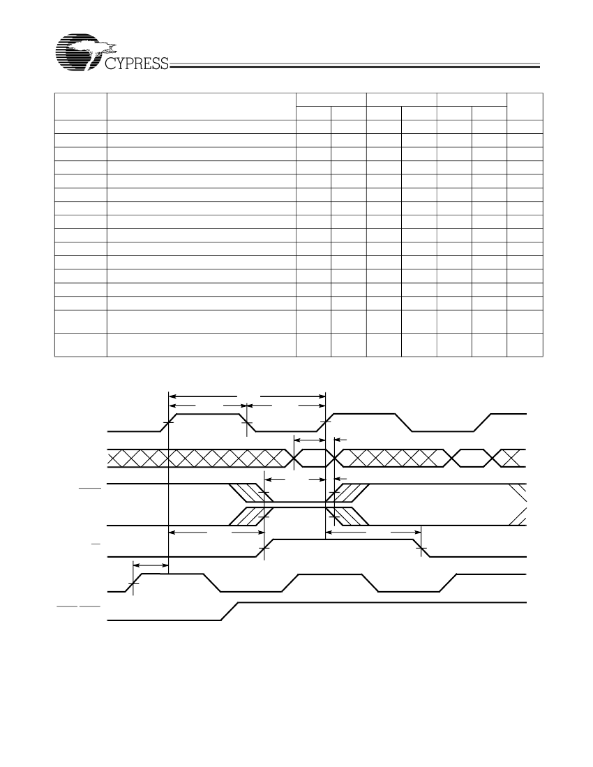
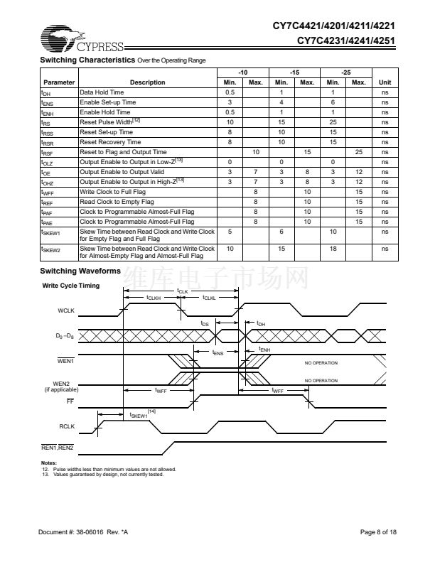
Switching Characteristics
Over the Operating Range
-10
Parameter
t
DH
t
ENS
t
ENH
t
RS
t
RSS
t
RSR
t
RSF
t
OLZ
t
OE
t
OHZ
t
WFF
t
REF
t
PAF
t
PAE
t
SKEW1
t
SKEW2
Data Hold Time
Enable Set-up Time
Enable Hold Time
Reset Pulse Width
[12]
Reset Set-up Time
Reset Recovery Time
Reset to Flag and Output Time
Output Enable to Output in Low-Z
Output Enable to Output Valid
Output Enable to Output in High-Z
Write Clock to Full Flag
Read Clock to Empty Flag
Clock to Programmable Almost-Full Flag
Clock to Programmable Almost-Full Flag
Skew Time between Read Clock and Write Clock
for Empty Flag and Full Flag
Skew Time between Read Clock and Write Clock
for Almost-Empty Flag and Almost-Full Flag
5
10
[13]
[13]
-15
Max.
Min.
1
4
1
15
10
10
10
15
0
7
7
8
8
8
8
6
15
3
3
8
8
10
10
10
10
10
18
0
3
3
Max.
Min.
1
6
1
25
15
15
-25
Max.
Unit
ns
ns
ns
ns
ns
ns
25
12
12
15
15
15
15
ns
ns
ns
ns
ns
ns
ns
ns
ns
ns
Description
Min.
0.5
3
0.5
10
8
8
0
3
3
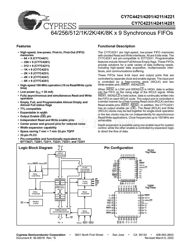
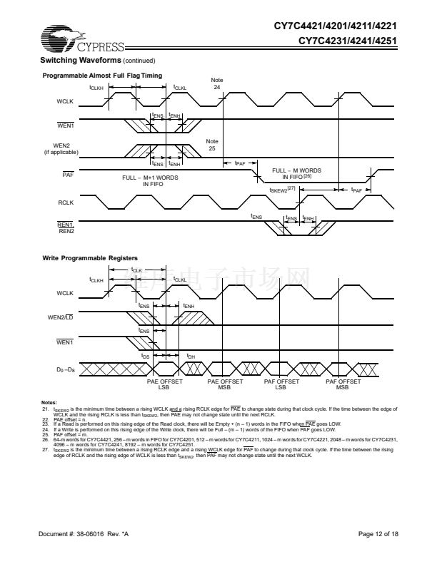
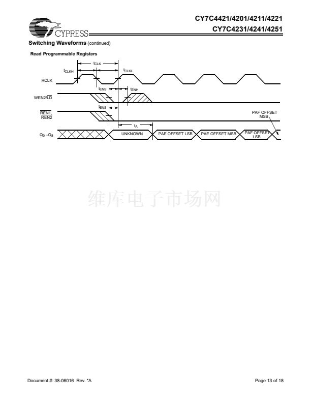
Switching Waveforms
Write Cycle Timing
t
CLKH
WCLK
t
DS
D
0
鈥揇
8
t
ENS
WEN1
t
ENH
NO OPERATION
t
CLK
t
CLKL
t
DH
WEN2
(if applicable)
FF
t
SKEW1
RCLK
NO OPERATION
t
WFF
t
WFF
[14]
REN1,REN2
Notes:
12. Pulse widths less than minimum values are not allowed.
13. Values guaranteed by design, not currently tested.
Document #: 38-06016 Rev. *A
Page 8 of 18


 1
1
 2
2
 3
3
 4
4
 5
5
 6
6
 7
7
 8
8
 9
9
 10
10
 11
11
 12
12
 13
13
 14
14
 15
15
 16
16
 17
17
 18
18
