CY7C4425/4205/4215
CY7C4225/4235/4245
Switching Characteristics
Over the Operating Range (continued)
7C42X5-10
Parameter
t
PAFsynch
t
PAEasynch
t
PAEsynch
t
HF
t
XO
t
XI
t
XIS
t
SKEW1
t
SKEW2
t
SKEW3
Description
Clock to Programmable Almost-Full Flag
(Synchronous mode, V
CC
/SMODE tied to V
SS
)
Clock to Programmable Almost-Empty Flag
[12]
(Asynchronous mode, V
CC
/SMODE tied to V
CC
)
Clock to Programmable Almost-Full Flag
(Synchronous mode, V
CC
/SMODE tied to V
SS
)
Clock to Half-Full Flag
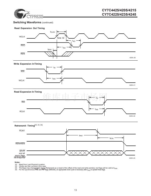
Clock to Expansion Out
Expansion in Pulse Width
Expansion in Set-Up Time
Skew Time between Read Clock and Write
Clock for Full Flag
Skew Time between Read Clock and Write
Clock for Empty Flag
Skew Time between Read Clock and Write
Clock for Programmable Almost Empty and Pro-
grammable Almost Full Flags.
3
4.5
5
5
10
Min.
Max.
8
12
8
12
7
6.5
5
6
6
15
7C42X5-15
Min.
Max.
10
16
10
16
10
10
10
10
10
18
7C42X5-25
Min.
Max.
15
20
15
20
15
14
15
12
12
20
7C42X5-35
Min.
Max. Unit
20
25
20
25
20
ns
ns
ns
ns
ns
ns
ns
ns
ns
ns
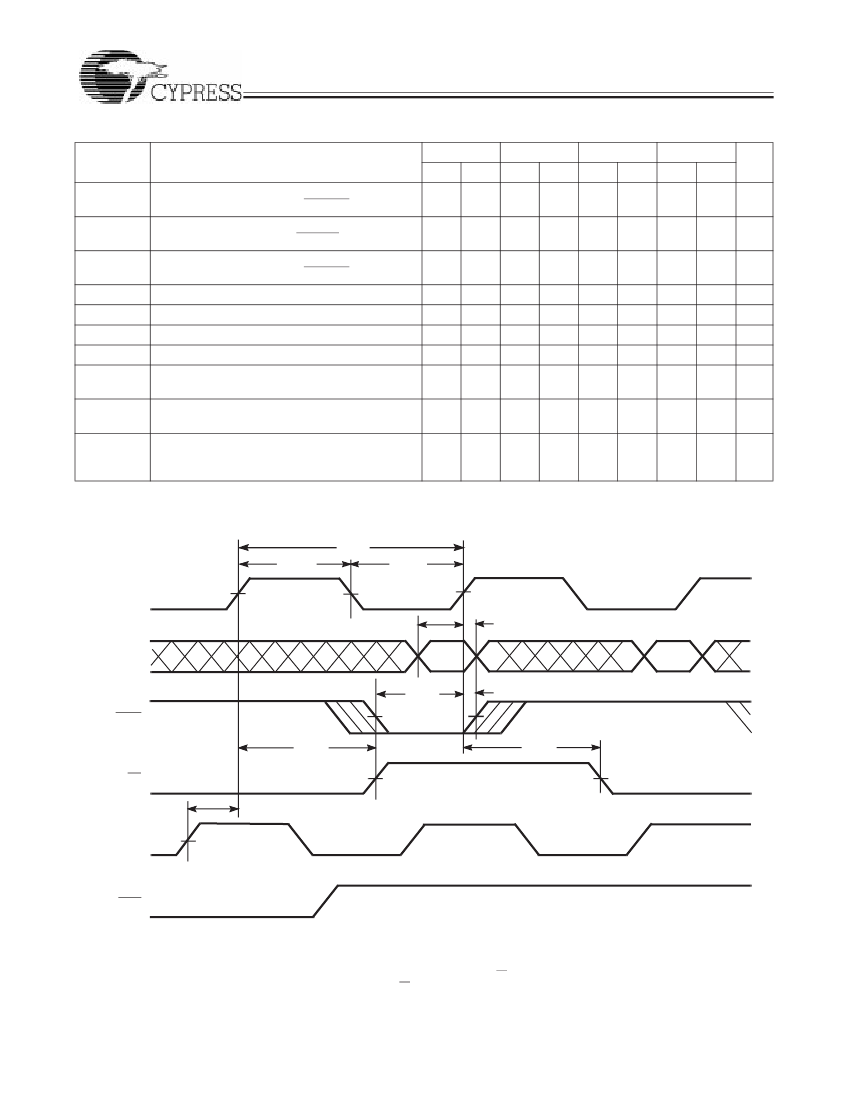
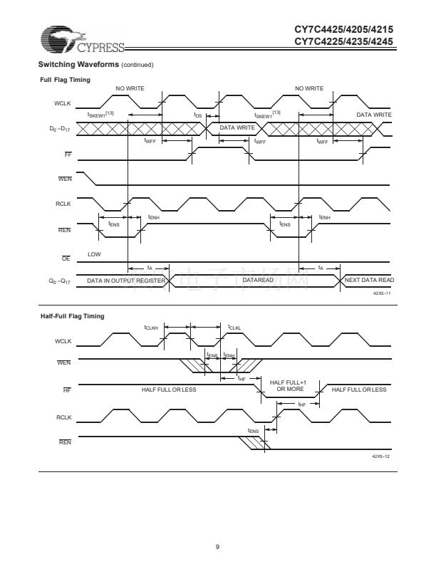
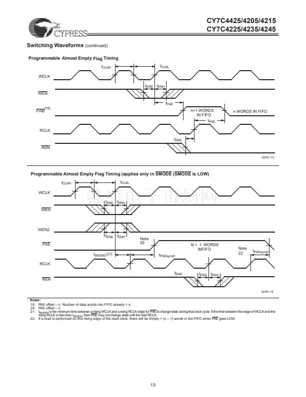
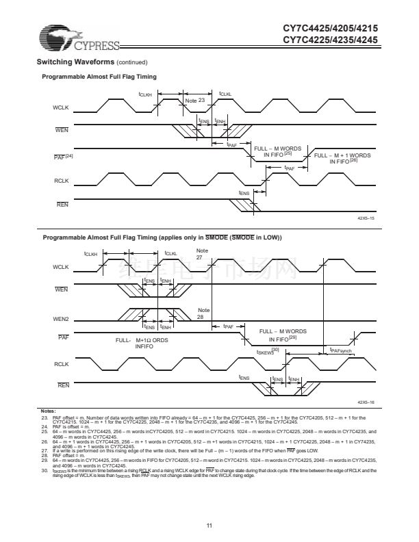
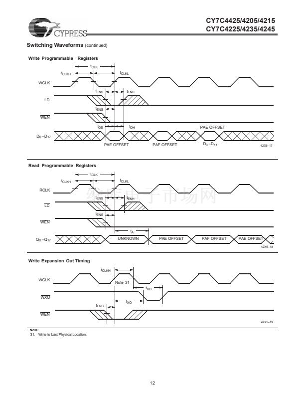
Switching Waveforms
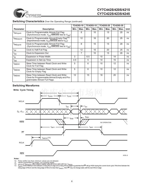
Write Cycle Timing
t
CLK
t
CLKH
WCLK
t
DS
D
0
鈥揇
17
t
ENS
WEN
t
WFF
FF
t
SKEW1[13]
RCLK
t
WFF
t
ENH
NO OPERATION
t
CLKL
t
DH
REN
42X5鈥?
Notes:
10. Pulse widths less than minimum values are not allowed.
11. Values guaranteed by design, not currently tested.
12.
PAFasynch
, t
PAEasynch
, after program register write will not be valid until 5 ns + t
PAF(E)
.
13. t
SKEW1
is the minimum time between a rising RCLK edge and a rising WCLK edge to guarantee that FF will go HIGH during the current clock cycle. If the time between the
rising edge of RCLK and the rising edge of WCLK is less than t
SKEW1
, then FF may not change state until the next WCLK edge.
6


 1
1
 2
2
 3
3
 4
4
 5
5
 6
6
 7
7
 8
8
 9
9
 10
10
 11
11
 12
12
 13
13
 14
14
 15
15
 16
16
 17
17
 18
18
 19
19
 20
20
 21
21
 22
22
 23
23
 24
24
 25
25
 26
26
