FOR
FOR
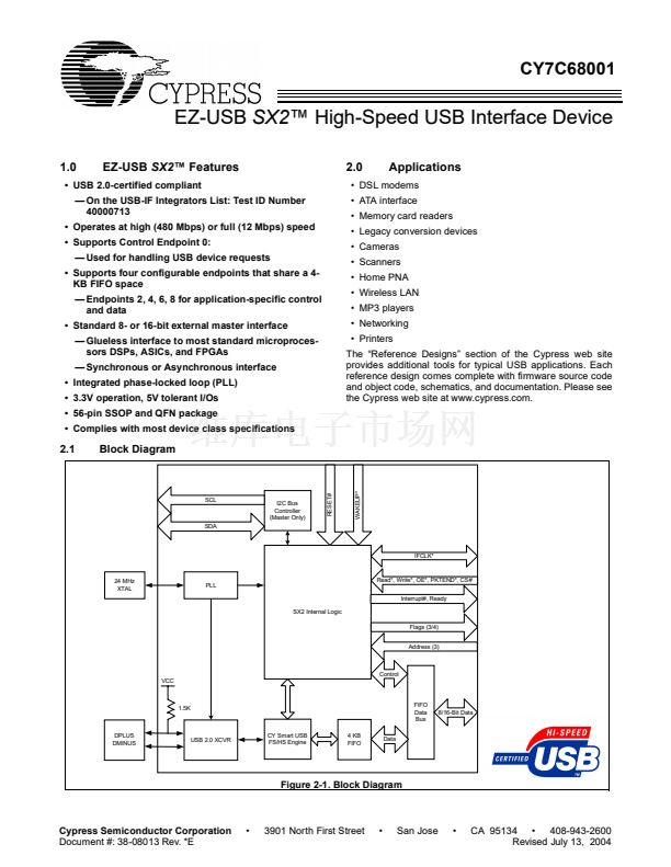
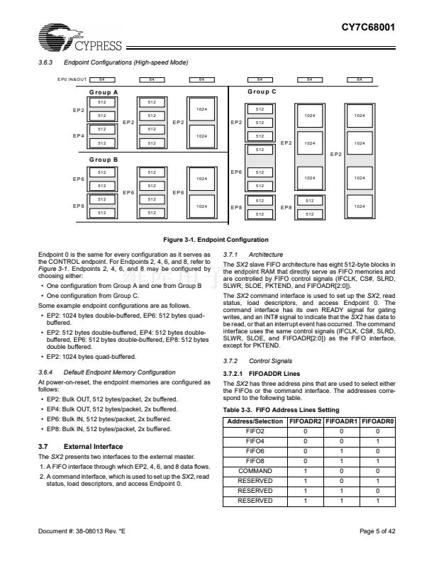
CY7C68001
4.0
Enumeration
5.0
Endpoint 0
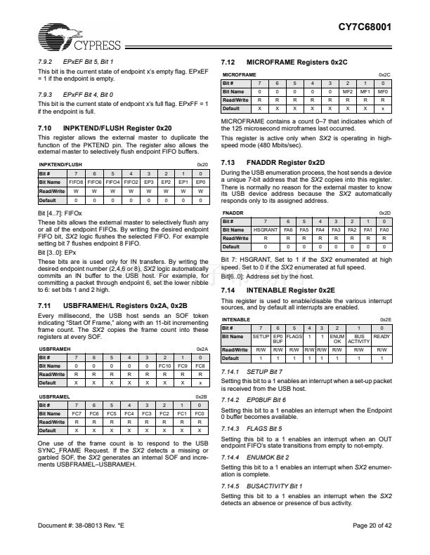
The
SX2
has two modes of enumeration. The first mode is
automatic through EEPROM boot load, as described in
Section 3.3. The second method is a manual load of the
descriptor or VID, PID, and DID as described below.
The
SX2
will automatically respond to USB chapter 9 requests
without any external master intervention. If the
SX2
receives
a request to which it cannot respond automatically, the
SX2
will notify the external master. The external master then has
the choice of responding to the request or stalling.
After the
SX2
receives a set-up packet to which it cannot
respond automatically, the
SX2
will assert a SETUP interrupt.
After the external master reads the Interrupt Status Byte to
determine that the interrupt source was the SETUP interrupt,
it can initiate a read request to the SETUP register, 0x32.
When the
SX2
sees a read request for the SETUP register, it
will present the first byte of set-up data to the external master.
Each additional read request will present the next byte of set-
up data, until all eight bytes have been read.
The external master can stall this request at this or any other
time. To stall a request, the external master initiates a write
request for the SETUP register, 0x32, and writes any non-zero
value to the register.
If this set-up request has a data phase, the
SX2
will then
interrupt the external master with an EP0BUF interrupt when
the buffer becomes available. The
SX2
determines the
direction of the set-up request and interrupts when either:
鈥?IN: the Endpoint 0 buffer becomes available to write to, or
鈥?OUT: the Endpoint 0 buffer receives a packet from the USB
host.
For an IN set-up transaction, the external master can write up
to 64 bytes at a time for the data phase. The steps to write a
packet are as follows:
1. Wait for an EP0BUF interrupt, indicating that the buffer is
available.
2. Initiate a write request for register 0x31.
3. Write one data byte.
4. Repeat steps 2 and 3 until either all the data or 64 bytes
have been written, whichever is less.
5. Write the number of bytes in this packet to the byte count
register, 0x33.
To send more than 64 bytes, the process is repeated. The
SX2
internally stores the length of the data phase that was
specified in the wLength field (bytes 6,7) of the set-up packet.
To send less than the requested amount of data, the external
master writes a packet that is less than 64 bytes, or if a multiple
of 64, the external master follows the data with a zero-length
packet. When the
SX2
sees a short or zero-length packet, it
will complete the set-up transfer by automatically completing
the handshake phase. The
SX2
will not allow more data than
the wLength field specified in the set-up packet. Note: the
PKTEND pin does not apply to Endpoint 0. The only way to
send a short or zero length packet is by writing to the byte
count register with the appropriate value.
4.1
Standard Enumeration
The
SX2
has 500 bytes of descriptor RAM into which the
external master may write its descriptor. The descriptor RAM
is accessed through register 0x30. To load a descriptor, the
external master does the following:
鈥?Initiate a Write Request to register 0x30.
鈥?Write two bytes (four command data transfers) that define
the length of the entire descriptor about to be transferred.
The LSB is written first, followed by the MSB.
[6]
鈥?Write the descriptor, one byte at a time until complete.
Note: the register address is only written once.
[6]
After the entire descriptor has been transferred, the
SX2
will
float the pull-up resistor connected to D+, and parse through
the descriptor to locate the individual descriptors. After the
SX2
has parsed the entire descriptor, the
SX2
will connect the
pull-up resistor and enumerate automatically. When enumer-
ation is complete, the
SX2
will notify the external master with
an ENUMOK interrupt.
The format and order of the descriptor should be as follows
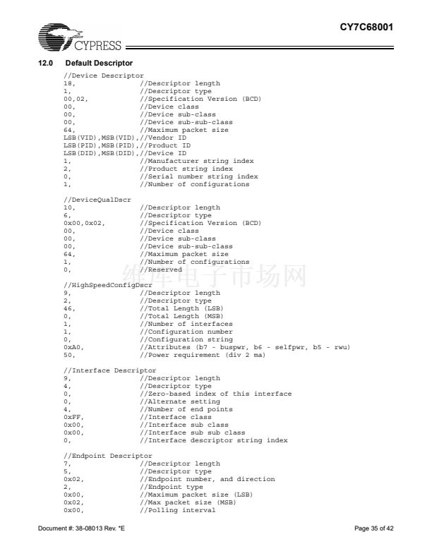
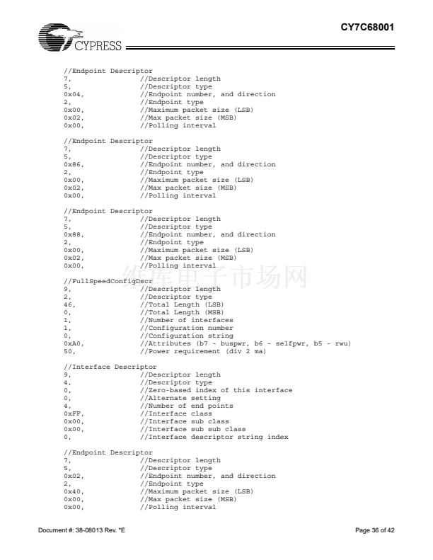
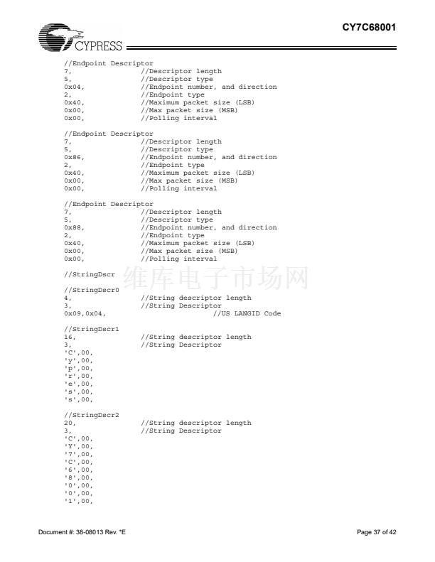
(see Section 12.0 for an example):
鈥?Device.
鈥?Device qualifier.
鈥?High-speed configuration, high-speed interface, high-
speed endpoints.
鈥?Full-speed configuration, full-speed interface, full-speed
endpoints.
鈥?String.
4.2
Default Enumeration
The external master may simply load a VID, PID, and DID and
use the default descriptor built into the
SX2.
To use the default
descriptor, the descriptor length described above must equal
6. After the external master has written the length, the VID,
PID, and DID must be written LSB, then MSB. For example, if
the VID, PID, and DID are 0x04B4, 0x1002, and 0x0001
respectively, then the external master does the following:
鈥?Initiates a Write Request to register 0x30.
鈥?Writes two bytes (four command data transfers) that define
the length of the entire descriptor about to be transferred.
In this case, the length is always six.
鈥?Writes the VID, PID, and DID bytes: 0xB4, 0x04, 0x02, 0x10,
0x01, 0x00 (in nibble format per the command protocol).
The default descriptor is listed in Section 12.0. The default
descriptor can be used as a starting point for a custom
descriptor.
Note:
6. These and all other data bytes must conform to the command protocol.
Document #: 38-08013 Rev. *E
Page 8 of 42


 1
1
 2
2
 3
3
 4
4
 5
5
 6
6
 7
7
 8
8
 9
9
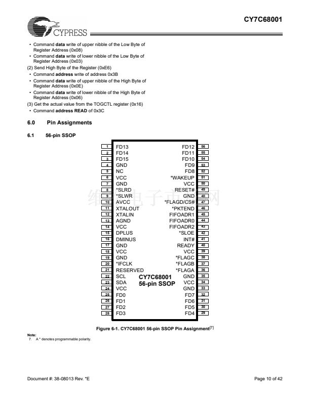 10
10
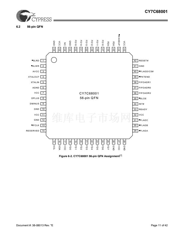 11
11
 12
12
 13
13
 14
14
 15
15
 16
16
 17
17
 18
18
 19
19
 20
20
 21
21
 22
22
 23
23
 24
24
 25
25
 26
26
 27
27
 28
28
 29
29
 30
30
 31
31
 32
32
 33
33
 34
34
 35
35
 36
36
 37
37
 38
38
 39
39
 40
40
 41
41
 42
42
 43
43
