EL7563
Applications Information
Circuit Description
General
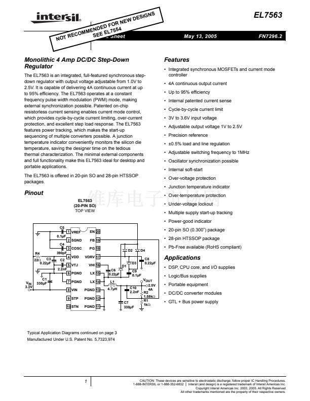
The EL7563 is a fixed frequency, current mode controlled
DC/DC converter with integrated N-channel power
MOSFETs and a high precision reference. The device
incorporates all the active circuitry required to implement a
cost effective, user-programmable 4A synchronous step-
down regulator suitable for use in DSP core power supplies.
By combining fused-lead packaging technology with an
efficient synchronous switching architecture, high power
output (10W) can be realized without the use of discrete
external heat sinks.
feedback is measured by the patented sensing scheme that
senses the inductor current flowing through the high-side
switch whenever it is conducting. At the beginning of each
oscillator period the high-side NMOS switch is turned on.
The comparator inputs are gated off for a minimum period of
time of about 150ns (LEB) after the high-side switch is
turned on to allow the system to settle. The Leading Edge
Blanking (LEB) period prevents the detection of erroneous
voltages at the comparator inputs due to switching noise. If
the inductor current exceeds the maximum current limit
(I
LMAX
) a secondary over-current comparator will terminate
the high-side switch on time. If I
LMAX
has not been reached,
the feedback voltage FB derived from the regulator output
voltage V
OUT
is then compared to the internal feedback
reference voltage. The resultant error voltage is summed
with the current feedback and slope compensation ramp.
The high-side switch remains on until all four comparator
inputs have summed to zero, at which time the high-side
switch is turned off and the low-side switch is turned on.
However, the maximum on-duty ratio of the high-side switch
is limited to 95%. In order to eliminate cross-conduction of
the high-side and low-side switches a 15ns break-before-
make delay is incorporated in the switch drive circuitry. The
output enable (EN) input allows the regulator output to be
disabled by an external logic control signal.
PWM Controller
The EL7563 regulates output voltage through the use of
current-mode controlled pulse width modulation. The three
main elements in a PWM controller are the feedback loop and
reference, a pulse width modulator whose duty cycle is
controlled by the feedback error signal, and a filter which
averages the logic level modulator output. In a step-down
(buck) converter, the feedback loop forces the time-averaged
output of the modulator to equal the desired output voltage.
Unlike pure voltage-mode control systems, current-mode
control utilizes dual feedback loops to provide both output
voltage and inductor current information to the controller. The
voltage loop minimizes DC and transient errors in the output
voltage by adjusting the PWM duty-cycle in response to
changes in line or load conditions. Since the output voltage is
equal to the time-averaged of the modulator output, the
relatively large LC time constant found in power supply
applications generally results in low bandwidth and poor
transient response. By directly monitoring changes in inductor
current via a series sense resistor the controller's response
time is not entirely limited by the output LC filter and can react
more quickly to changes in line and load conditions. This feed-
forward characteristic also simplifies AC loop compensation
since it adds a zero to the overall loop response. Through
proper selection of the current-feedback to voltage-feedback
ratio the overall loop response will approach a one-pole
system. The resulting system offers several advantages over
traditional voltage control systems, including simpler loop
compensation, pulse by pulse current limiting, rapid response
to line variation and good load step response.
The heart of the controller is an input direct summing
comparator which sum voltage feedback, current feedback,
slope compensation ramp and power tracking signals
together. Slope compensation is required to prevent system
instability that occurs in current-mode topologies operating
at duty-cycles greater than 50% and is also used to define
the open-loop gain of the overall system. The slope
compensation is fixed internally and optimized for 500mA
inductor ripple current. The power tracking will not contribute
any input to the comparator steady-state operation. Current
Output Voltage Setting
In general:
R
2
铮?/div>
铮?/div>
V
OUT
=
0.992V
脳 铮?/div>
1
+ ------
铮?/div>
-
R
1
铮?/div>
铮?/div>
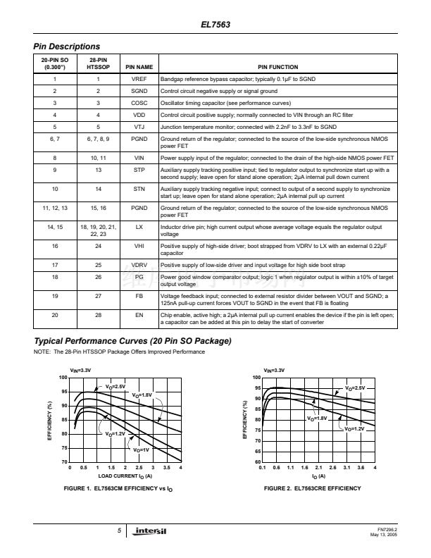
However, due to the relatively low open loop gain of the
system, gain errors will occur as the output voltage and loop-
gain is changed. This is shown in the performance curves. A
100nA pull-up current from FB to V
DD
forces V
OUT
to GND
in the event that FB is floating.
NMOS Power FETs and Drive Circuitry
The EL7563 integrates low on-resistance (30m鈩? NMOS
FETs to achieve high efficiency at 4A. In order to use an
NMOS switch for the high-side drive it is necessary to drive
the gate voltage above the source voltage (L
X
). This is
accomplished by bootstrapping the V
HI
pin above the L
X
voltage with an external capacitor CV
HI
and internal switch
and diode. When the low-side switch is turned on and the L
X
voltage is close to GND potential, capacitor CV
HI
is charged
through internal switch to V
DRV
, typically 6V with external
charge-pump. At the beginning of the next cycle the high-
side switch turns on and the L
X
pins begin to rise from GND
to V
IN
potential. As the L
X
pin rises the positive plate of
capacitor CV
HI
follows and eventually reaches a value of
V
DRV
+V
IN
, typically 9V, for V
IN
=3.3V. This voltage is then
level shifted and used to drive the gate of the high-side FET,
via the V
HI
pin. A value of 0.22碌F for CV
HI
is recommended.
10
FN7296.2
May 13, 2005
EL7563CM相关型号PDF文件下载
-
型号
版本
描述
厂商
下载
-
英文版
100V High Side Driver
-
英文版
100V High Side Driver
INTERSIL [...
-
英文版
High Frequency PWM Step-Up Regulator
-
英文版
High Frequency PWM Step-Up Regulator
INTERSIL [...
-
英文版
White LED Step-Up Regulator
-
英文版
White LED Step-Up Regulator
INTERSIL [...
-
英文版
High Frequency PWM Step-Up Regulator
-
英文版
High Frequency PWM Step-Up Regulator
INTERSIL [...
-
英文版
600kHz/1.2MHz PWM Step-Up Regulator
IRF
-
英文版
600kHz/1.2MHz PWM Step-Up Regulator
-
英文版
600kHz/1.2MHz PWM Step-Up Regulator
INTERSIL [...
-
英文版
600kHz/1.2MHz PWM Step-Up Regulator
IRF [Inter...
-
英文版
4-Channel DC/DC Controller
-
英文版
4-Channel DC/DC Controller
INTERSIL [...
-
英文版
Monolithic 600mA Step-Down Regulator with Low Quiescent Curr...
-
英文版
Monolithic 600mA Step-Down Regulator with Low Quiescent Curr...
INTERSIL [...
-
英文版
Monolithic 1A Step-Down Regulator with Low Quiescent Current
-
英文版
Monolithic 1A Step-Down Regulator with Low Quiescent Current
INTERSIL [...
-
英文版
Monolithic 2A Step-Down Regulator
-
英文版
Monolithic 2A Step-Down Regulator
INTERSIL [...


 1
1
 2
2
 3
3
 4
4
 5
5
 6
6
 7
7
 8
8
 9
9
 10
10
 11
11
 12
12
 13
13
 14
14
 15
15
 16
16
