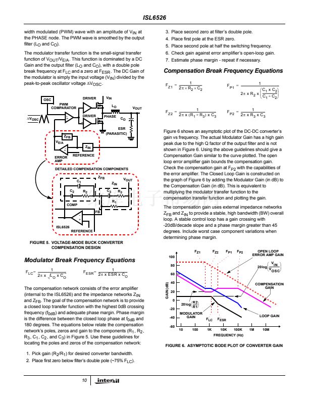
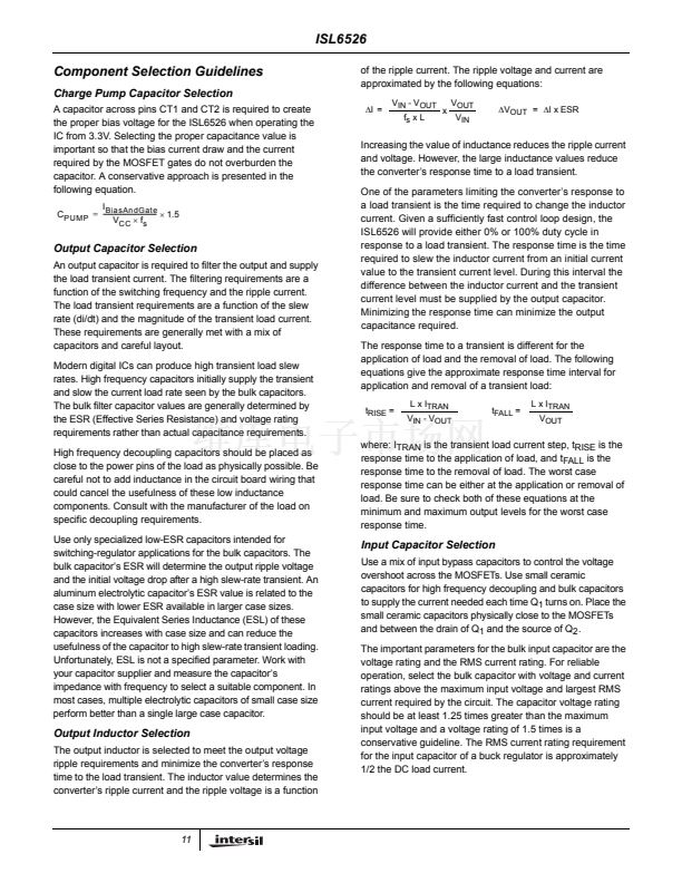
.
鈥?/div>
V
BOOT2
of no less than 0.1碌F. The tolerance of the ceramic capacitor
should also be considered when selecting the final bootstrap
capacitance value.
A fast recovery diode is recommended when selecting a
bootstrap diode to reduce the impact of reverse recovery
charge loss. Otherwise, the recovery charge, Q
RR
, would
have to be added to the gate charge of the MOSFET and
taken into consideration when calculating the minimum
bootstrap capacitance.
Typical gate charge values for MOSFETs considered in
these types of applications range from 20 to 100nC. Since
the voltage drop across Q
LOWER
is negligible, V
BOOT1
is
simply V
CPVOUT
- V
D
. A schottky diode is recommended to
minimize the voltage drop across the bootstrap capacitor
during the on-time of the upper MOSFET. Initial calculations
with V
BOOT2
no less than 4V will quickly help narrow the
bootstrap capacitor range.
For example, consider an upper MOSFET is chosen with a
maximum gate charge, Q
g
, of 100nC. Limiting the voltage
drop across the bootstrap capacitor to 1V results in a value
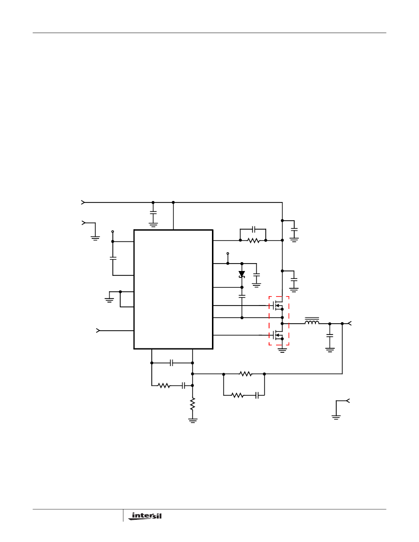
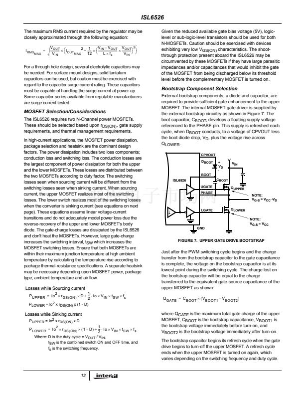
ISL6526 DC-DC Converter Application
Circuit
Figure 8 shows an application circuit of a DC-DC Converter.
Detailed information on the circuit, including a complete Bill-
of-Materials and circuit board description, can be found in
Application Note AN9994.
3.3V
C
11
C
0.1碌F
TP
1
4
CT1
ISL6526
C
4
0.22碌F
5
CT2
CPGND
GND
BOOT
13
C
7
CPVOUT
3
D
1
C
5
10碌F
CERAMIC
0.1碌F
L
1
11
VCC
OCSET
U
1
6
TP
3
R
1
9.76k鈩?/div>
C
2
1000pF
C
3
GND
10
1
C
6
1碌F
UGATE
PHASE
14
12
2.5V @ 5A
C
8,9
ENABLE
9
ENABLE
COMP
8
C
10
33pF
R
2
C
11
LGATE
FB
7
2
Q
1
R
3
2.26k鈩?/div>
R
4
R
5
1.07k鈩?/div>
124鈩?/div>
C
12
8200pF
GND
6.49k鈩?5600pF
FIGURE 8. 3.3V TO 2.5V 5A DC-DC CONVERTER
Component Selection Notes:
C
3,8,9
- Each 150碌F, Panasonic EEF-UE0J151R or Equivalent.
D1 - 30mA Schottky Diode, MA732 or Equivalent
L
1
- 1碌H Inductor, Panasonic P/N ETQ-P6F1ROSFA or Equivalent.
Q
1
- Fairchild MOSFET; ITF86110DK8.
13


 1
1
 2
2
 3
3
 4
4
 5
5
 6
6
 7
7
 8
8
 9
9
 10
10
 11
11
 12
12
 13
13
 14
14
 15
15
