current. I
usually appropriate. If 2.4M鈩?is chosen for R2 (I
鈩?/div>
) = V
HB
(mV)
When hysteresis is obtained in this manner for the
MAX982/MAX9_3, the same hysteresis applies to both
comparators.
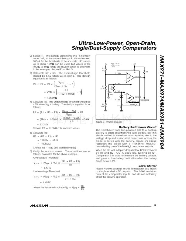
Window Detector
The MAX9_3 is ideal for making window detectors
(undervoltage/overvoltage detectors). The schematic is
shown in Figure 5, with component values selected for a
4.5V undervoltage threshold and a 5.5V overvoltage
threshold. Choose different thresholds by changing the
values of R1, R2, and R3. To prevent chatter at the
output when the supply voltage is close to a threshold,
hysteresis has been added using R4 and R5. Taken
alone, OUTA would provide an active-low undervoltage
indication, and OUTB would give an active-low
overvoltage indication. Wired-ORing the two outputs
provides an active-high, power-good signal.
The design procedure is as follows:
1) Choose the required hysteresis level and calculate
values for R4 and R5 according to the formulas in
the
Hysteresis (MAX9_1/MAX982/MAX9_3)
section.
In this example, 卤5mV of hysteresis has been added
at the comparator input
(V
H
= V
HB
/ 2). This means
that the hysteresis apparent at V
IN
will be larger
because of the input resistor divider.
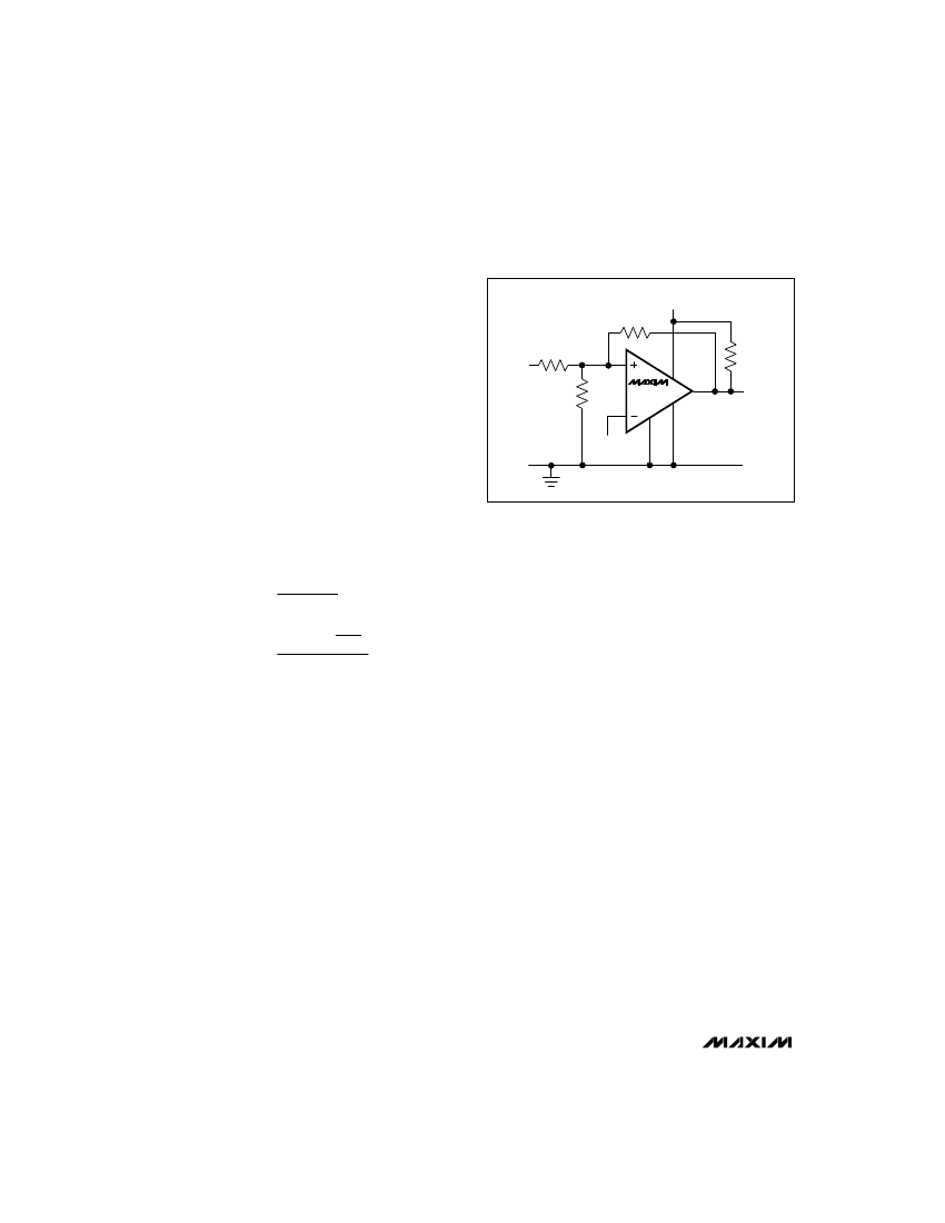
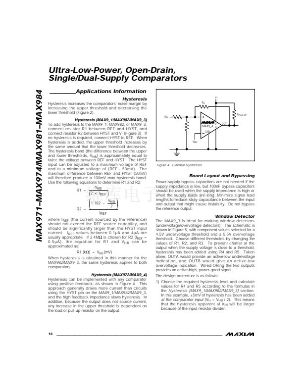
Hysteresis (MAX972/MAX9_4)
Hysteresis can be implemented with any comparator
using positive feedback, as shown in Figure 4. This
approach generally draws more current than circuits
using the HYST pin on the MAX9_1/MAX982/MAX9_3,
and the high feedback impedance slows hysteresis. In
addition, because the output does not source current,
any increase in the upper threshold is dependent on
the load or pull-up resistor on the output.
10
______________________________________________________________________________________


 1
1
 2
2
 3
3
 4
4
 5
5
 6
6
 7
7
 8
8
 9
9
 10
10
 11
11
 12
12
 13
13
 14
14
 15
15
 16
16
