DS1621
THF
= Temperature High Flag. This bit will be set to 鈥?鈥?when the temperature is greater than or
equal to the value of TH. It will remain 鈥?鈥?until reset by writing 鈥?鈥?into this location or removing power
from the device. This feature provides a method of determining if the DS1621 has ever been subjected to
temperatures above TH while power has been applied.
TLF
= Temperature Low Flag. This bit will be set to 鈥?鈥?when the temperature is less than or equal
to the value of TL. It will remain 鈥?鈥?until reset by writing 鈥?鈥?into this location or removing power from
the device. This feature provides a method of determining if the DS1621 has ever been subjected to
temperatures below TL while power has been applied.
NVB = Nonvolatile Memory Busy flag. 鈥?鈥?= Write to an E
2
memory cell in progress, 鈥?鈥?=
nonvolatile memory is not busy. A copy to E
2
may take up to 10 ms.
POL
= Output Polarity Bit. 鈥?鈥?= active high, 鈥?鈥?= active low. This bit is nonvolatile.
1SHOT = One Shot Mode. If 1SHOT is 鈥?鈥? the DS1621 will perform one temperature conversion upon
receipt of the Start Convert T protocol. If 1SHOT is 鈥?鈥? the DS1621 will continuously perform
temperature conversions. This bit is nonvolatile.
For typical thermostat operation the DS1621 will operate in continuous mode. However, for applications
where only one reading is needed at certain times or to conserve power, the one鈥搒hot mode may be used.
Note that the thermostat output (T
OUT
) will remain in the state it was in after the last valid temperature
conversion cycle when operating in one鈥搒hot mode.
2鈥揥IRE SERIAL DATA BUS
The DS1621 supports a bidirectional 2鈥搘ire bus and data transmission protocol. A device that sends data
onto the bus is defined as a transmitter, and a device receiving data as a receiver. The device that controls
the message is called a 鈥渕aster." The devices that are controlled by the master are 鈥渟laves." The bus must
be controlled by a master device which generates the serial clock (SCL), controls the bus access, and
generates the START and STOP conditions. The DS1621 operates as a slave on the 2鈥搘ire bus.
Connections to the bus are made via the open鈥揹rain I/O lines SDA and SCL.
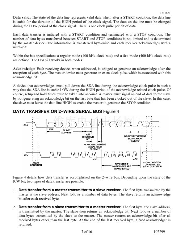
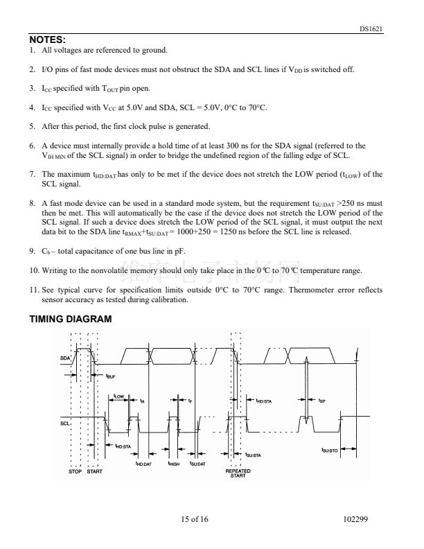
The following bus protocol has been defined (See Figure 4):
鈥?/div>
Data transfer may be initiated only when the bus is not busy.
鈥?/div>
During data transfer, the data line must remain stable whenever the clock line is HIGH. Changes in
the data line while the clock line is high will be interpreted as control signals.
Accordingly, the following bus conditions have been defined:
Bus not busy:
Both data and clock lines remain HIGH.
Start data transfer:
A change in the state of the data line, from HIGH to LOW, while the clock is HIGH,
defines a START condition.
Stop data transfer:
A change in the state of the data line, from LOW to HIGH, while the clock line is
HIGH, defines the STOP condition.
6 of 16
102299


 1
1
 2
2
 3
3
 4
4
 5
5
 6
6
 7
7
 8
8
 9
9
 10
10
 11
11
 12
12
 13
13
 14
14
 15
15
 16
16
