The second parameter for choosing the inductor is the desired current ripple in the inductor. Normally, it is
advisable to work with a ripple of less than 20% of the average inductor current. A smaller ripple reduces the
magnetic hysteresis losses in the inductor, as well as output voltage ripple and EMI. But in the same way,
regulation time rises at load changes. In addition, a larger inductor increases the total system costs. With these
parameters, it is possible to calculate the value for the inductor by using Equation 4:
鈭?/div>
I
L
is the ripple current in the inductor, i.e., 40%
脳
I
L
. In this example,
the desired inductor has the value of 4 碌H. With this calculated value and the calculated currents, it is possible to
choose a suitable inductor. In typical applications, a 4.7-碌H inductance is recommended. The device has been
optimized to operate with inductance values between 2.2 碌H and 10 碌H. Nevertheless, operation with higher
inductance values may be possible in some applications. Detailed stability analysis is then recommended. Care
must be taken because load transients and losses in the circuit can lead to higher currents as estimated in
Equation 4. Also, the losses in the inductor caused by magnetic hysteresis losses and copper losses are a major
parameter for total circuit efficiency.
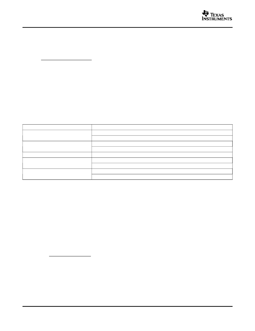
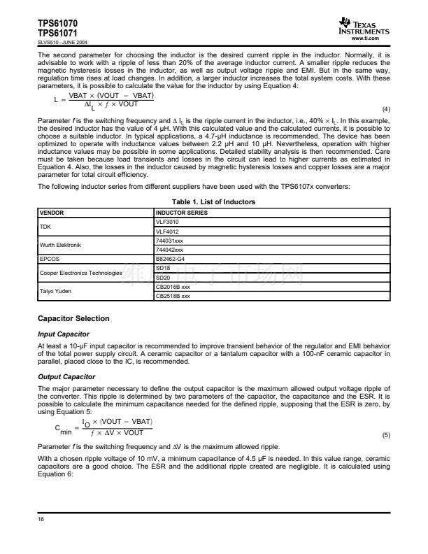
The following inductor series from different suppliers have been used with the TPS6107x converters:
Table 1. List of Inductors
VENDOR
TDK
Wurth Elektronik
EPCOS
Cooper Electronics Technologies
Taiyo Yuden
INDUCTOR SERIES
VLF3010
VLF4012
744031xxx
744042xxx
B82462-G4
SD18
SD20
CB2016B xxx
CB2518B xxx
Capacitor Selection
Input Capacitor
At least a 10-碌F input capacitor is recommended to improve transient behavior of the regulator and EMI behavior
of the total power supply circuit. A ceramic capacitor or a tantalum capacitor with a 100-nF ceramic capacitor in
parallel, placed close to the IC, is recommended.
Output Capacitor
The major parameter necessary to define the output capacitor is the maximum allowed output voltage ripple of
the converter. This ripple is determined by two parameters of the capacitor, the capacitance and the ESR. It is
possible to calculate the minimum capacitance needed for the defined ripple, supposing that the ESR is zero, by
using Equation 5:
I
VOUT
*
VBAT
C
+
O
min
茠
DV
VOUT
(5)
Parameter
f
is the switching frequency and
鈭哣
is the maximum allowed ripple.
With a chosen ripple voltage of 10 mV, a minimum capacitance of 4.5 碌F is needed. In this value range, ceramic
capacitors are a good choice. The ESR and the additional ripple created are negligible. It is calculated using
Equation 6:
16


 1
1
 2
2
 3
3
 4
4
 5
5
 6
6
 7
7
 8
8
 9
9
 10
10
 11
11
 12
12
 13
13
 14
14
 15
15
 16
16
 17
17
 18
18
 19
19
 20
20
 21
21
