Lattice Semiconductor
ispPAC30 Preliminary Data Sheet
other as necessary to achieve higher gains, for example. Precision gain and offset con铿乬urations can be imple-
mented using different combinations of IA鈥檚, MDAC鈥檚 and VREF鈥檚 to condition signals using a common summing
junction to deliver the desired output result. The combination of analog input and summing node route options
make the ispPAC30 very powerful in enabling so many different circuit possibilities. Examples of possible circuits
are included in the ispPAC30 applications literature.
Output Ampli铿乪r Functional Modes
The ispPAC30 output ampli铿乪rs (OA鈥檚) can be con铿乬ured to act as wideband ampli铿乪rs, lowpass 铿乴ters, integrators
or comparators. Each mode is determined by SRAM (or E
2
con铿乬uration memory at turn-on) control bits that open
and close feedback elements around the OA鈥檚. All available modes of OA operation can be con铿乬ured during the
design phase using PAC-Designer software or during normal operation via JTAG or SPI serial interface control.
Ampli铿乪r/Filter Mode
When con铿乬ured as a wideband ampli铿乪r, an ispPAC30鈥檚 OA feedback resistor connection is closed and the feed-
back capacitor set to its minimum value. The feedback capacitance set is required to maintain necessary stability.
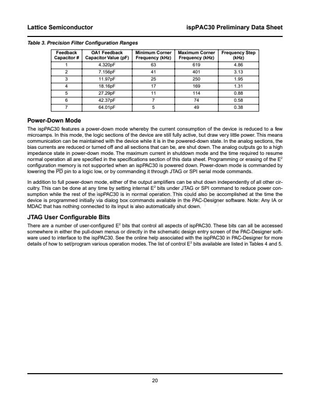
When used in 铿乴ter mode, the ispPAC30 differs from the wideband ampli铿乪r in that it has seven alternative feedback
capacitor values available to form the lowpass 铿乴ter corner frequencies. See Table 3 for these values (listed as the
maximum corner frequencies in the precision 铿乴ter range table). The capacitor values are trimmed for each device
to achieve an absolute pole frequency with an accuracy guaranteed to that given in the speci铿乧ations section. The
铿乺st order 铿乴ter formed using the OA in this manner is not the only way a 铿乴ter can be implemented using the
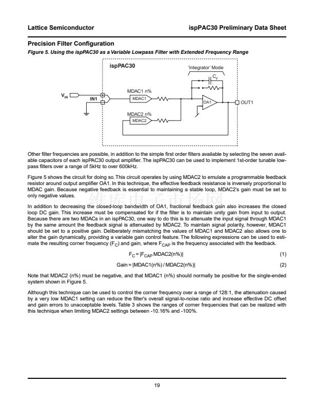
ispPAC30. In the following precision 铿乴tering section, an example is given for using an OA in integrator mode and
providing proportional feedback by putting one of the MDAC鈥檚 into the feedback loop. When calculating equivalent
time constants for ispPAC30 in 铿乴ter mode, a nominal resistance of 50k鈩?can be assumed. The frequencies called
out in PAC-Designer that are associated with individual feedback capacitor values are computed based on the
measured 鈥?dB frequency of a single IA/OA combination (gain=1). Again, absolute accuracy is guaranteed as
listed in the 铿乴ter speci铿乧ations section for all devices shipped.
Integrator Mode
In integrator mode, an OA鈥檚 feedback capacitor is closed and the feedback resistor is open. Operation then
becomes that of an integrator, with the expected non-ideal effects of a real operational ampli铿乪r (having 铿乶ite gain-
bandwidth properties). The gain-phase simulator in the PAC-Designer will give the user a very good representation
of these 铿乺st-order effects on ideal operation. The effective time-constant of any given integrator con铿乬uration can
be computed knowing the feedback capacitor value and that an IA in a gain =1 will yield an effective input resis-
tance, R, equal to 50k鈩?(1 time constant = 2 x
蟺
x RC). This value of R is divided by the gain setting of the IA, so in
a gain of 10 for example, R is equal to 5k鈩? When an MDAC is used as the input to an OA con铿乬ured as an integra-
tor, the effective R is equal to 50k鈩?divided by the fraction of the input signal passed by the MDAC. For example, if
the MDAC is set to a code that results in passing 50% of the input signal, then R is equal to 50k鈩?0.5 or 100k鈩?
This can, of course, be used to advantage to either extend the effective time constant range or to 铿乶e tune it.
Comparator Mode
In comparator mode, both the feedback capacitor and resistor are opened around the OA. Also, the internal com-
pensation of the OA is altered to improve comparator output characteristics. Since only one input is available to the
OA in comparator mode, instead of the normally expected two, a slightly different approach is required to realize a
true comparison function. This is done by using the reference voltage and summing it with the value it is to be com-
pared with. Whenever the input to be compared is greater than the reference input value the OA output is high and
when it is less, the OA output is low. The logic sense of this comparator output can be controlled at will by selecting
either plus or minus gains in the IA/MDAC input sections. When examined closely, it may be observed that compar-
ator mode operation appears identical to that of the integrator mode with a minimum feedback capacitance. This is
true except in comparator mode the output compensation of the OA is altered to get optimum switching times. That
means using the OA in other linear modes without this compensation enabled will likely result in unstable opera-
tion. In PAC-Designer, the default con铿乬uration modes will not allow this to happen.
18


 1
1
 2
2
 3
3
 4
4
 5
5
 6
6
 7
7
 8
8
 9
9
 10
10
 11
11
 12
12
 13
13
 14
14
 15
15
 16
16
 17
17
 18
18
 19
19
 20
20
 21
21
 22
22
 23
23
 24
24
 25
25
 26
26
 27
27
 28
28
 29
29
 30
30
