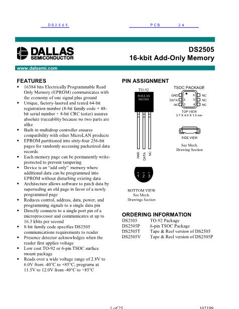
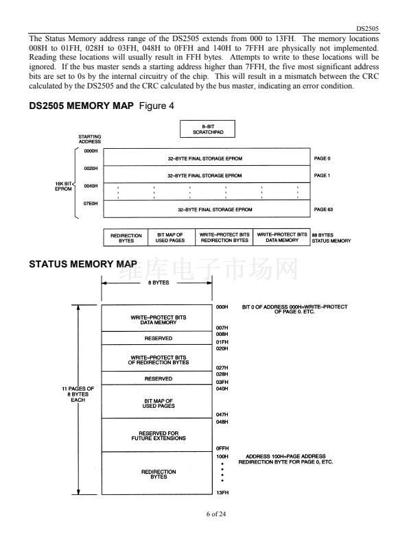
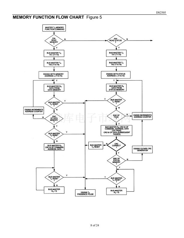
DS2505
Hardware Configuration
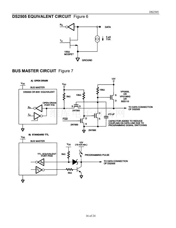
The 1-Wire bus has only a single line by definition; it is important that each device on the bus be able to
drive it at the appropriate time. To facilitate this, each device attached to the 1-Wire bus must have an
open drain connection or 3-state outputs. The DS2505 is an open drain part with an internal circuit
equivalent to that shown in Figure 6. The bus master can be the same equivalent circuit. If a bi-
directional pin is not available, separate output and input pins can be tied together.
The bus master requires a pullup resistor at the master end of the bus, with the bus master circuit
equivalent to the one shown in Figures 7a and 7b. The value of the pullup resistor should be
approximately 5 k鈩?for short line lengths.
A multidrop bus consists of a 1-Wire bus with multiple slaves attached. The 1-Wire bus has a maximum
data rate of 16.3 kbits per second. If the bus master is also required to perform programming of the
EPROM portions of the DS2505, a programming supply capable of delivering up to 10 milliamps at
12 volts for 480 碌s is required. The idle state for the 1-Wire bus is high. If, for any reason, a transaction
needs to be suspended, the bus MUST be left in the idle state if the transaction is to resume. If this does
not occur and the bus is left low for more than 120 碌s, one or more of the devices on the bus may be
reset.
Transaction Sequence
The sequence for accessing the DS2505 via the 1-Wire port is as follows:
Initialization
ROM Function Command
Memory Function Command
Read/Write Memory/Status
INITIALIZATION
All transactions on the 1-Wire bus begin with an initialization sequence. The initialization sequence
consists of a reset pulse transmitted by the bus master followed by a presence pulse(s) transmitted by the
slave(s).
The presence pulse lets the bus master know that the DS2505 is on the bus and is ready to operate. For
more details, see the 鈥?-Wire Signaling鈥?section.
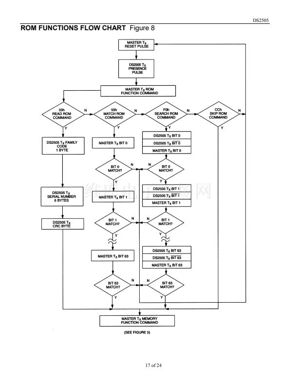
ROM FUNCTION COMMANDS
Once the bus master has detected a presence, it can issue one of the four ROM function commands. All
ROM function commands are 8 bits long. A list of these commands follows (refer to flowchart in
Figure 8):
Read ROM [33H]
This command allows the bus master to read the DS2505鈥檚 8-bit family code, unique 48鈥揵it serial
number, and 8-bit CRC. This command can be used only if there is a single DS2505 on the bus. If more
than one slave is present on the bus, a data collision will occur when all slaves try to transmit at the same
time (open drain will produce a wired-AND result).
15 of 24


 1
1
 2
2
 3
3
 4
4
 5
5
 6
6
 7
7
 8
8
 9
9
 10
10
 11
11
 12
12
 13
13
 14
14
 15
15
 16
16
 17
17
 18
18
 19
19
 20
20
 21
21
 22
22
 23
23
 24
24
