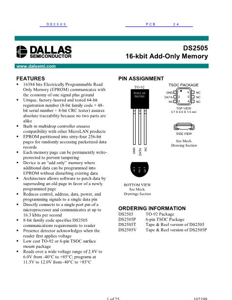
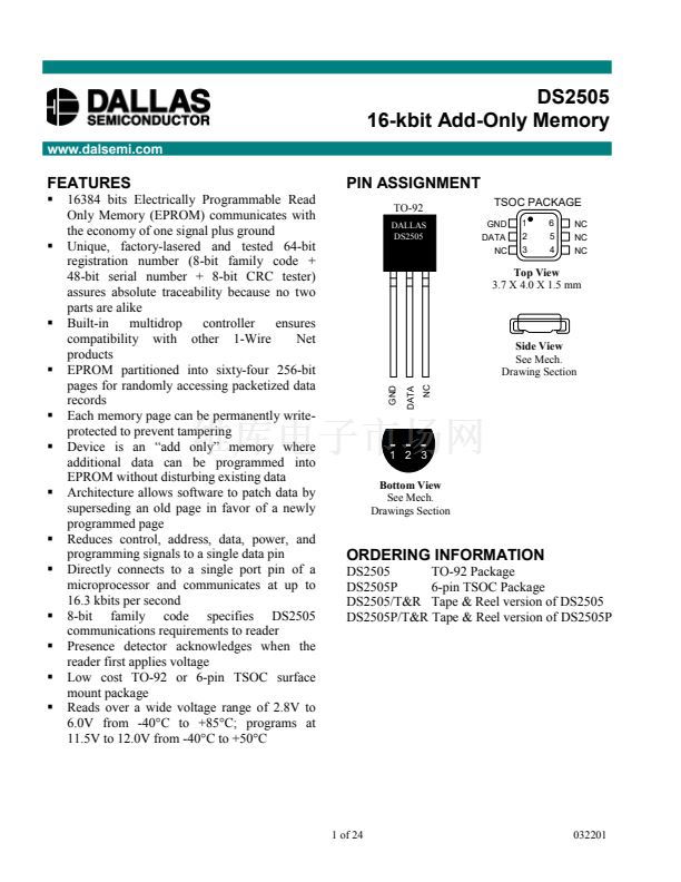
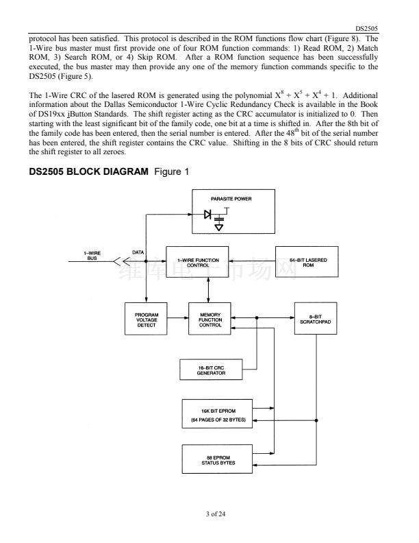
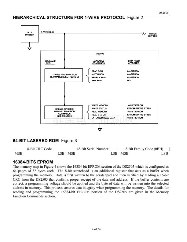
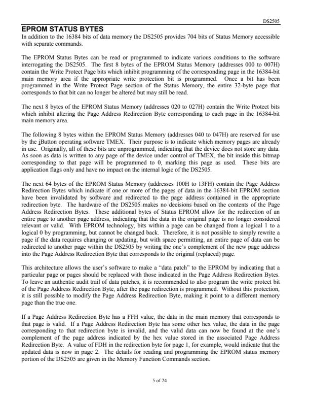
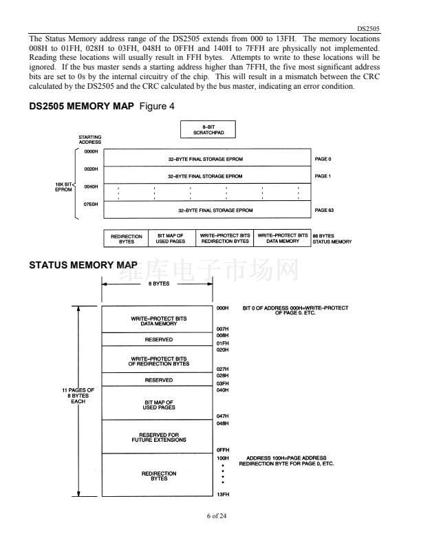
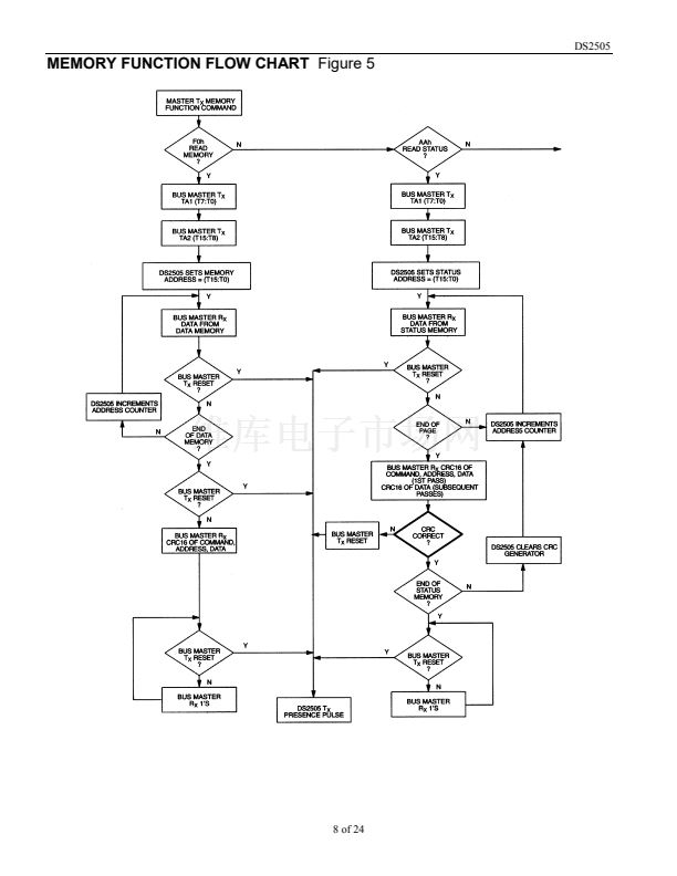
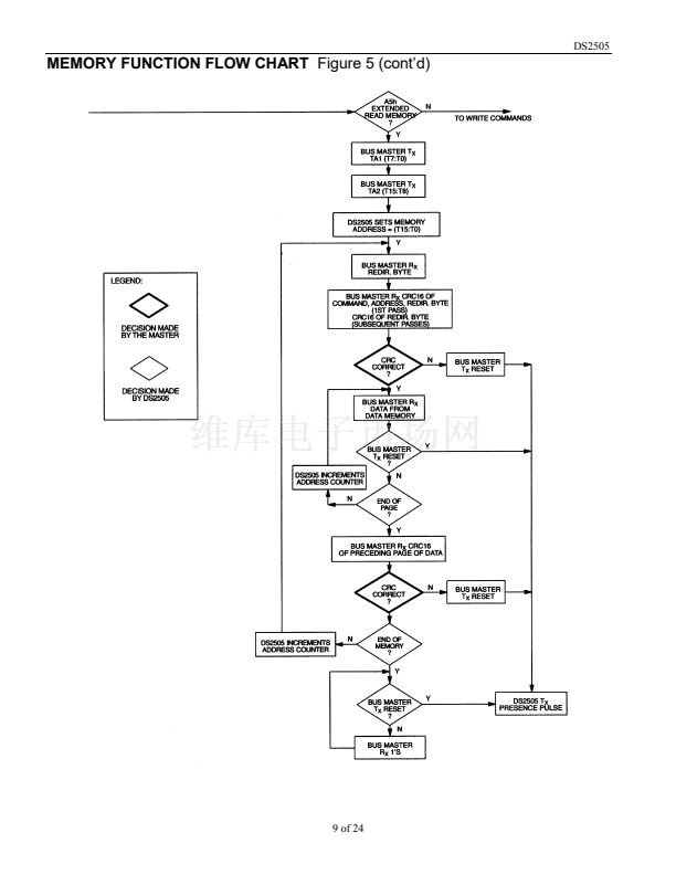
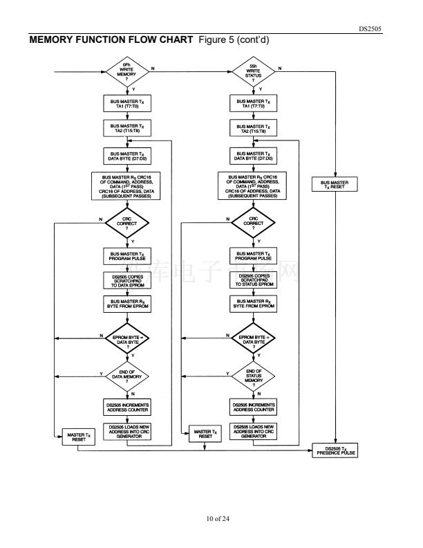
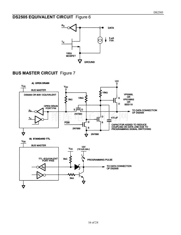
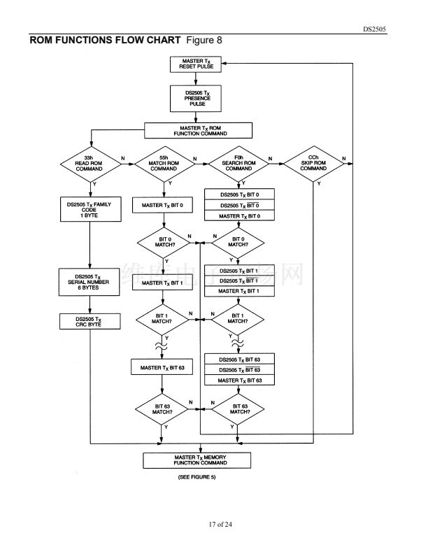
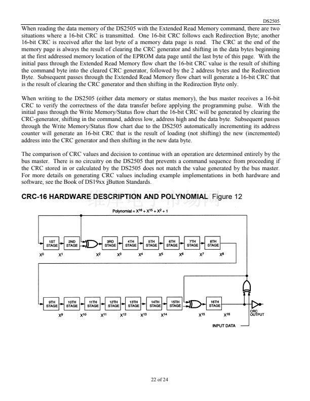
DS2505
(Figure 11) should be applied for 480 碌s, after which the bus master returns the data line to an idle high
state controlled by the pullup resistor. Note that due to the high voltage programming requirements for
any 1-Wire EPROM device, it is not possible to multidrop non-EPROM based 1-Wire devices with the
DS2505 during programming. An internal diode within the non-EPROM based 1-Wire devices will
attempt to clamp the data line at approximately 8 volts and could potentially damage these devices.
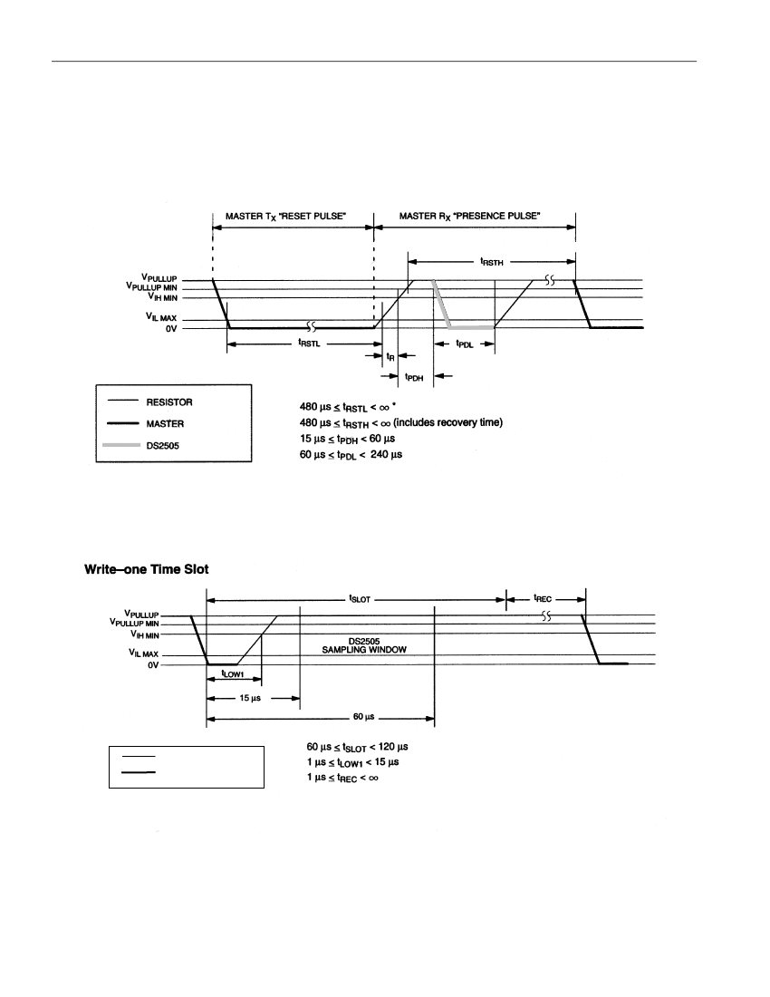
INITIALIZATION PROCEDURE 鈥淩ESET AND PRESENCE PULSES鈥?/div>
Figure 9
* In order not to mask interrupt signaling by other devices on the 1-Wire bus, t
RSTL
+ t
R
should always be
less than 960 碌s.
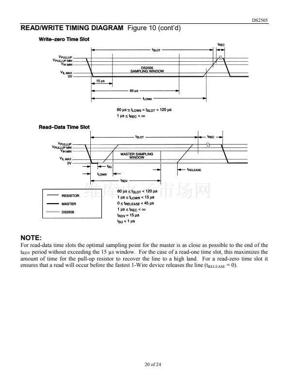
READ/WRITE TIMING DIAGRAM
Figure 10
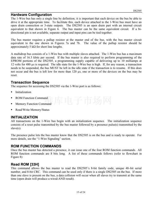
RESISTOR
MASTER
19 of 24


 1
1
 2
2
 3
3
 4
4
 5
5
 6
6
 7
7
 8
8
 9
9
 10
10
 11
11
 12
12
 13
13
 14
14
 15
15
 16
16
 17
17
 18
18
 19
19
 20
20
 21
21
 22
22
 23
23
 24
24
