DS2505
MEMORY FUNCTION COMMANDS
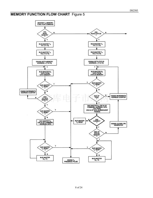
The 鈥淢emory Function Flow Chart鈥?(Figure 5) describes the protocols necessary for accessing the
various data fields within the DS2505. The Memory Function Control section, 8-bit scratchpad, and the
Program Voltage Detect circuit combine to interpret the commands issued by the bus master and create
the correct control signals within the device. A 3-byte protocol is issued by the bus master. It is
comprised of a command byte to determine the type of operation and two address bytes to determine the
specific starting byte location within a data field. The command byte indicates if the device is to be read
or written. Writing data involves not only issuing the correct command sequence but also providing a
12-volt programming voltage at the appropriate times. To execute a write sequence, a byte of data is first
loaded into the scratchpad and then programmed into the selected address. Write sequences always occur
a byte at a time. To execute a read sequence, the starting address is issued by the bus master and data is
read from the part beginning at that initial location and continuing to the end of the selected data field or
until a reset sequence is issued. All bits transferred to the DS2505 and received back by the bus master
are sent least significant bit first.
READ MEMORY [F0H]
The Read Memory command is used to read data from the 16384-bit EPROM data field. The bus master
follows the command byte with a 2-byte address (TA1=(T7:T0), TA2=(T15:T8)) that indicates a starting
byte location within the data field. With every subsequent read data time slot the bus master receives data
from the DS2505 starting at the initial address and continuing until the end of the 16384-bit data field is
reached or until a reset pulse is issued. If reading occurs through the end of memory space, the bus
master may issue sixteen additional read time slots and the DS2505 will respond with a 16-bit CRC of the
command, address bytes and all data bytes read from the initial starting byte through the last byte of
memory. This CRC is the result of clearing the CRC generator and then shifting in the command byte
followed by the 2 address bytes and the data bytes beginning at the first addressed memory location and
continuing through to the last byte of the EPROM data memory. After the CRC is received by the bus
master, any subsequent read time slots will appear as logical 1s until a reset pulse is issued. Any reads
ended by a reset pulse prior to reaching the end of memory will not have the 16-bit CRC available.
Typically a 16-bit CRC would be stored with each page of data to ensure rapid, error-free data transfers
that eliminate having to read a page multiple times to determine if the received data is correct or not.
(See Book of DS19xx iButton Standards, Chapter 7 for the recommended file structure to be used with
the 1-Wire environment.) If CRC values are imbedded within the data, a Reset Pulse may be issued at the
end of memory space during a Read Memory command.
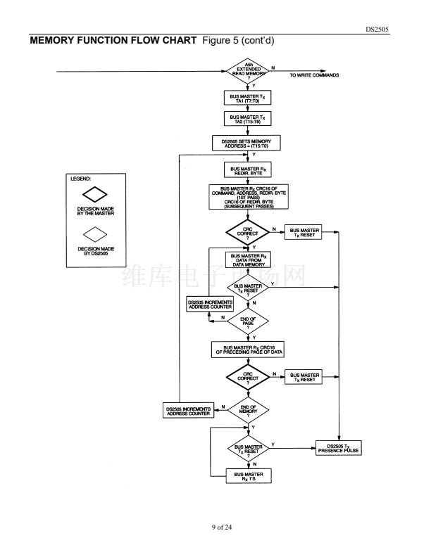
READ STATUS [AAH]
The Read Status command is used to read data from the EPROM Status data field. The bus master
follows the command byte with a 2-byte address (TA1=(T7:T0), TA2=(T15:T8)) that indicates a starting
byte location within the data field. With every subsequent read data time slot the bus master receives data
from the DS2505 starting at the supplied address and continuing until the end of an 8-byte page of the
EPROM Status data field is reached. At that point the bus master will receive a 16-bit CRC of the
command byte, address bytes and status data bytes. This CRC is computed by the DS2505 and read back
by the bus master to check if the command word, starting address and data were received correctly. If the
CRC read by the bus master is incorrect, a reset pulse must be issued and the entire sequence must be
repeated.
7 of 24


 1
1
 2
2
 3
3
 4
4
 5
5
 6
6
 7
7
 8
8
 9
9
 10
10
 11
11
 12
12
 13
13
 14
14
 15
15
 16
16
 17
17
 18
18
 19
19
 20
20
 21
21
 22
22
 23
23
 24
24
