.鈥?/div>
13.4.2
POWER-UP TIMER (PWRT)
If V
DD
falls below V
BOR
(parameter D005) for longer
than T
BOR
(parameter #35), the brown-out situation
will reset the device. If V
DD
falls below V
BOR
for less
than T
BOR
, a reset may not occur.
Once the brown-out occurs, the device will remain in
brown-out reset until V
DD
rises above V
BOR
. The
power-up timer then keeps the device in reset for
T
PWRT
(parameter #33). If V
DD
should fall below V
BOR
during T
PWRT
, the brown-out reset process will restart
when V
DD
rises above V
BOR
with the power-up timer
reset. Since the device is intended to operate at 5V
nominal only, the brown-out detect is always enabled
and the device will reset when Vdd falls below the
brown-out threshold. This device is unique in that the
4鈥DT timer will not activate after a brown-out if
PWRTE = 1 (inactive).
13.4.5
TIME-OUT SEQUENCE
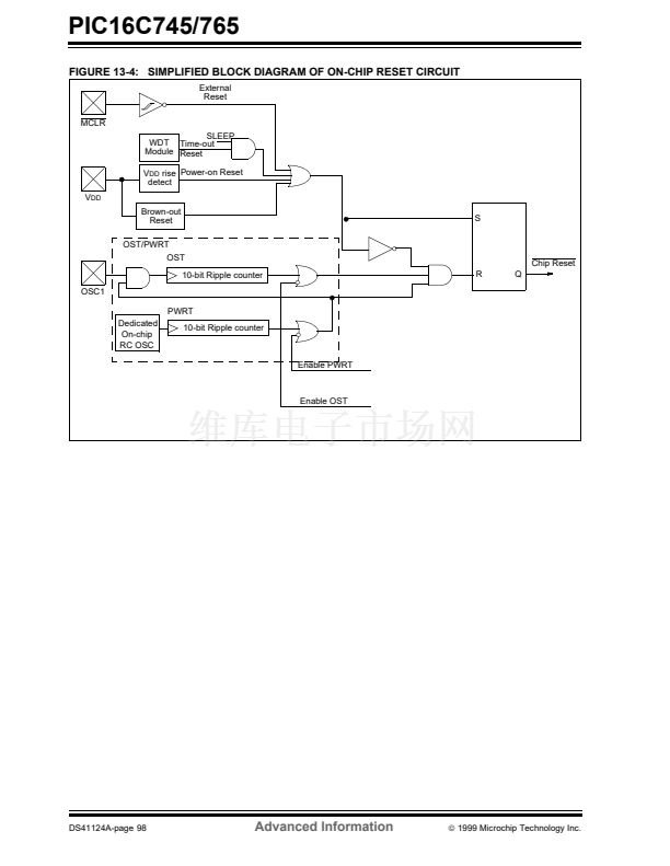
The Power-up Timer provides a fixed 72 ms nominal
time-out on power-up from the POR. The PWRT oper-
ates on an internal RC oscillator. The device is kept in
reset as long as the PWRT is active. The PWRT鈥檚 time
delay allows V
DD
to rise to an acceptable level. A con-
figuration bit is provided to enable/disable the PWRT.
The power-up time delay will vary from chip to chip due
to V
DD
, temperature and process variation. See DC
parameters for details (T
PWRT
, parameter #33).
13.4.3
OSCILLATOR START-UP TIMER (OST)
On power-up, the time-out sequence is as follows: The
PWRT delay starts (if enabled) when a POR reset
occurs. Then OST starts counting 1024 oscillator
cycles when PWRT ends (HS). When the OST ends,
the device comes out of RESET.
If MCLR is kept low long enough, the time-outs will
expire. Bringing MCLR high will begin execution imme-
diately. This is useful for testing purposes or to synchro-
nize more than one PIC16CXX device operating in
parallel.
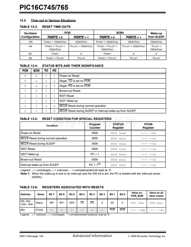
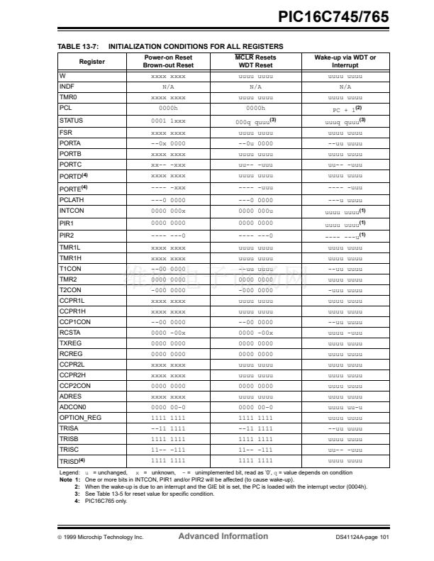
Table 13-5 shows the reset conditions for the STATUS,
PCON and PC registers, while Table 13-7 shows the
reset conditions for all the registers.
13.4.6
POWER CONTROL/STATUS REGISTER
(PCON)
The Oscillator Start-up Timer provides a delay of 1024
oscillator cycles (from OSC1 input) after the PWRT
delay. This ensures that the crystal oscillator or resona-
tor has started and stabilized.
The OST time-out is invoked only for HS mode and only
on power-on reset or wake-up from SLEEP.
The Brown-out Reset Status bit, BOR, is unknown on a
POR. It must be set by the user and checked on subse-
quent resets to see if bit BOR was cleared, indicating a
BOR occurred. The BOR bit is not predictable if the
brown-out reset circuitry is disabled.
The Power-on Reset Status bit, POR, is cleared on a
POR and unaffected otherwise. The user must set this
bit following a POR and check it on subsequent resets
to see if it has been cleared.
漏
1999 Microchip Technology Inc.
Advanced Information
DS41124A-page 99


 1
1
 2
2
 3
3
 4
4
 5
5
 6
6
 7
7
 8
8
 9
9
 10
10
 11
11
 12
12
 13
13
 14
14
 15
15
 16
16
 17
17
 18
18
 19
19
 20
20
 21
21
 22
22
 23
23
 24
24
 25
25
 26
26
 27
27
 28
28
 29
29
 30
30
 31
31
 32
32
 33
33
 34
34
 35
35
 36
36
 37
37
 38
38
 39
39
 40
40
 41
41
 42
42
 43
43
 44
44
 45
45
 46
46
 47
47
 48
48
 49
49
 50
50
 51
51
 52
52
 53
53
 54
54
 55
55
 56
56
 57
57
 58
58
 59
59
 60
60
 61
61
 62
62
 63
63
 64
64
 65
65
 66
66
 67
67
 68
68
 69
69
 70
70
 71
71
 72
72
 73
73
 74
74
 75
75
 76
76
 77
77
 78
78
 79
79
 80
80
 81
81
 82
82
 83
83
 84
84
 85
85
 86
86
 87
87
 88
88
 89
89
 90
90
 91
91
 92
92
 93
93
 94
94
 95
95
 96
96
 97
97
 98
98
 99
99
 100
100
 101
101
 102
102
 103
103
 104
104
 105
105
 106
106
 107
107
 108
108
 109
109
 110
110
 111
111
 112
112
 113
113
 114
114
 115
115
 116
116
 117
117
 118
118
 119
119
 120
120
 121
121
 122
122
 123
123
 124
124
 125
125
 126
126
 127
127
 128
128
 129
129
 130
130
 131
131
 132
132
 133
133
 134
134
 135
135
 136
136
 137
137
 138
138
 139
139
 140
140
 141
141
 142
142
 143
143
 144
144
 145
145
 146
146
 147
147
 148
148
 149
149
 150
150
 151
151
 152
152
 153
153
 154
154
 155
155
 156
156
 157
157
 158
158
