鈥?/div>
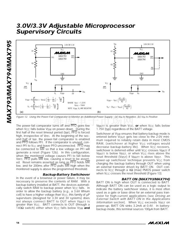
V
D
R3
V
H
= R1 (V
PFT
+ V
PFH
)
(
(a)
(b)
WHERE V
PFT
= 1.237V
V
PFH
= 10mV
V
D
= DIODE FORWARD VOLTAGE DROP
V
L
= V
TRIP
Figure 16. Adding Hysteresis to the Power-Fail Comparator: (a) Symmetrical Hysteresis, (b) Hysteresis Only on Rising V
IN
timeout period (because PFI is below the PFI thresh-
old), the IC will test the voltage level on PFO, find that it
is low, and incorrectly decide to enter freshness seal
mode. If V
CC
is later removed, the backup battery will
not be connected to OUT and any devices powered by
OUT will lose power.
Applications that do not use the PFO comparator need
not be affected by this problem. Simply connect PFI to
V
CC
and PFO will be driven high during all reset time-
out periods. Freshness seal mode can be entered only
when PFO is low.
The IC is under revision to correct this problem. The
revised IC will disable PFO during all reset timeout peri-
ods including MR-initiated ones. This revision will not
affect applications that either do not use MR or do not
use PFO, but could affect applications that require the
use of the PFO output during MR-initiated reset timeout
periods. The revised ICs are expected to be available
in late 1996. For technical assistance, please contact
Maxim Applications at 1-800-998-8800 or at
http:// www. maxim-ic.com.
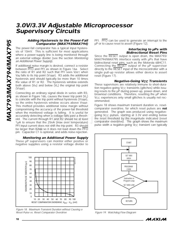
V
CC
V
CC
RESET
RESET
V
CC
RESET
GENERATOR
N
碌P
MAX793
MAX794
MAX795
GND
GND
Figure 17. Interfacing to 碌Ps with Bidirectional Reset I/O
______________________________________________________________________________________
17


 1
1
 2
2
 3
3
 4
4
 5
5
 6
6
 7
7
 8
8
 9
9
 10
10
 11
11
 12
12
 13
13
 14
14
 15
15
 16
16
 17
17
 18
18
 19
19
 20
20
