3.0V/3.3V Adjustable Microprocessor
Supervisory Circuits
MAX793/MAX794/MAX795
Adding Hysteresis to the Power-Fail
Comparator (MAX793/MAX794)
The power-fail comparator has a typical input hystere-
sis of 10mV. This is sufficient for most applications
where a power-supply line is being monitored through
an external voltage divider (see the section
Monitoring
an Additional Power Supply).
If additional noise margin is desired, connect a resistor
between PFO and PFI as shown in Figure 16a. Select
the ratio of R1 and R2 such that PFI sees V
PFT
when
V
IN
falls to its trip point (V
TRIP
). R3 adds the additional
hysteresis and should typically be more than 10 times
the value of R1 or R2. The hysteresis window extends
both above (V
H
) and below (V
L
) the original trip point
(V
TRIP
).
Connecting an ordinary signal diode in series with R3,
as shown in Figure 16b, causes the lower trip point (V
L
)
to coincide with the trip point without hysteresis (V
TRIP
),
so the entire hysteresis window occurs above V
TRIP
.
This method provides additional noise margin without
compromising the accuracy of the power-fail threshold
when the monitored voltage is falling. It is useful for
accurately detecting when a voltage falls past a thresh-
old. The current through R1 and R2 should be at least
1碌A to ensure that the 25nA (max over temperature)
PFI input current does not shift the trip point. R3 should
be larger than 82k鈩?so it does not load down the PFO
pin. Capacitor C1 is optional, and adds noise rejection.
PFI. PFO can be used to generate an interrupt to the
碌P or to cause reset to assert (Figure 12).
Interfacing to 碌Ps with
Bidirectional Reset Pins
Since the RESET output is open drain, the MAX793/
MAX794/MAX795 interface easily with 碌Ps that have
bidirectional reset pins, such as the Motorola 68HC11.
Connecting the RESET output of the 碌P supervisor
directly to the RESET input of the microcontroller with a
single pull-up resistor allows either device to assert
reset (Figure 17).
Negative-Going V
CC
Transients
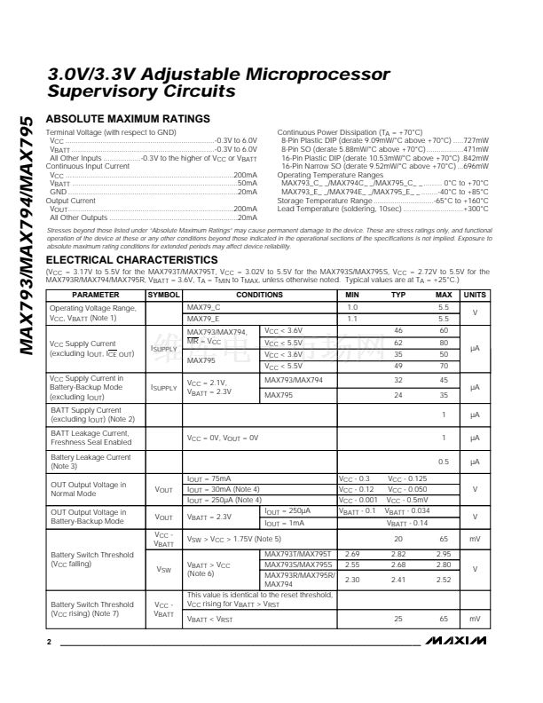
These supervisors are relatively immune to short-dura-
tion negative-going V
CC
transients (glitches) while issu-
ing resets to the 碌P during power-up, power-down, and
brownout conditions. Therefore, resetting the 碌P when
V
CC
experiences only small glitches is usually not rec-
ommended.
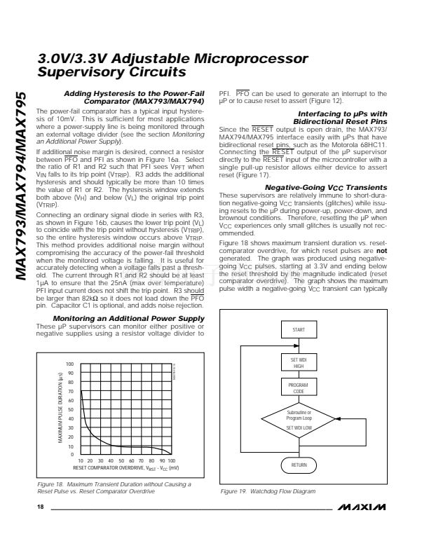
Figure 18 shows maximum transient duration vs. reset-
comparator overdrive, for which reset pulses are
not
generated. The graph was produced using negative-
going V
CC
pulses, starting at 3.3V and ending below
the reset threshold by the magnitude indicated (reset
comparator overdrive). The graph shows the maximum
pulse width a negative-going V
CC
transient can typically
Monitoring an Additional Power Supply
These 碌P supervisors can monitor either positive or
negative supplies using a resistor voltage divider to
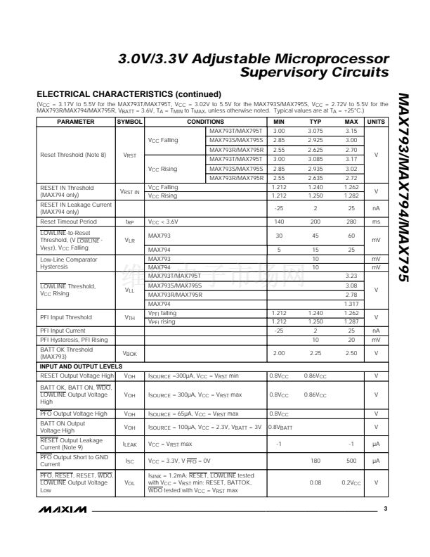
START
MAXIMUM PULSE DURATION (碌s)
90
80
70
60
50
40
30
20
10
0
10 20
30 40
50 60 70
80
MAX793-FIG 18
100
SET WDI
HIGH
PROGRAM
CODE
Subroutine or
Program Loop
SET WDI LOW
90 100
RESET COMPARATOR OVERDRIVE, V
RST
- V
CC
(mV)
RETURN
Figure 18. Maximum Transient Duration without Causing a
Reset Pulse vs. Reset Comparator Overdrive
18
Figure 19. Watchdog Flow Diagram
______________________________________________________________________________________


 1
1
 2
2
 3
3
 4
4
 5
5
 6
6
 7
7
 8
8
 9
9
 10
10
 11
11
 12
12
 13
13
 14
14
 15
15
 16
16
 17
17
 18
18
 19
19
 20
20
