3.0V/3.3V Adjustable Microprocessor
Supervisory Circuits
MAX793/MAX794/MAX795
ABSOLUTE MAXIMUM RATINGS
Terminal Voltage (with respect to GND)
V
CC
........................................................................-0.3V to 6.0V
V
BATT
.....................................................................-0.3V to 6.0V
All Other Inputs ..................-0.3V to the higher of V
CC
or V
BATT
Continuous Input Current
V
CC
.................................................................................200mA
V
BATT
................................................................................50mA
GND ..................................................................................20mA
Output Current
V
OUT
................................................................................200mA
All Other Outputs ..............................................................20mA
Continuous Power Dissipation (T
A
= +70掳C)
8-Pin Plastic DIP (derate 9.09mW/掳C above +70掳C) .....727mW
8-Pin SO (derate 5.88mW/掳C above +70掳C)..................471mW
16-Pin Plastic DIP (derate 10.53mW/掳C above +70掳C) .842mW
16-Pin Narrow SO (derate 9.52mW/掳C above +70掳C) ...696mW
Operating Temperature Ranges
MAX793_C_ _/MAX794C_ _/MAX795_C_ _ ......... 0掳C to +70掳C
MAX793_E_ _/MAX794E_ _/MAX795_E_ _ ........-40掳C to +85掳C
Storage Temperature Range .............................-65掳C to +160掳C
Lead Temperature (soldering, 10sec) .............................+300掳C
Stresses beyond those listed under 鈥淎bsolute Maximum Ratings鈥?may cause permanent damage to the device. These are stress ratings only, and functional
operation of the device at these or any other conditions beyond those indicated in the operational sections of the specifications is not implied. Exposure to
absolute maximum rating conditions for extended periods may affect device reliability.
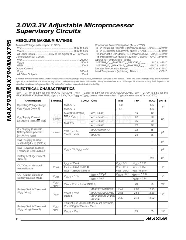
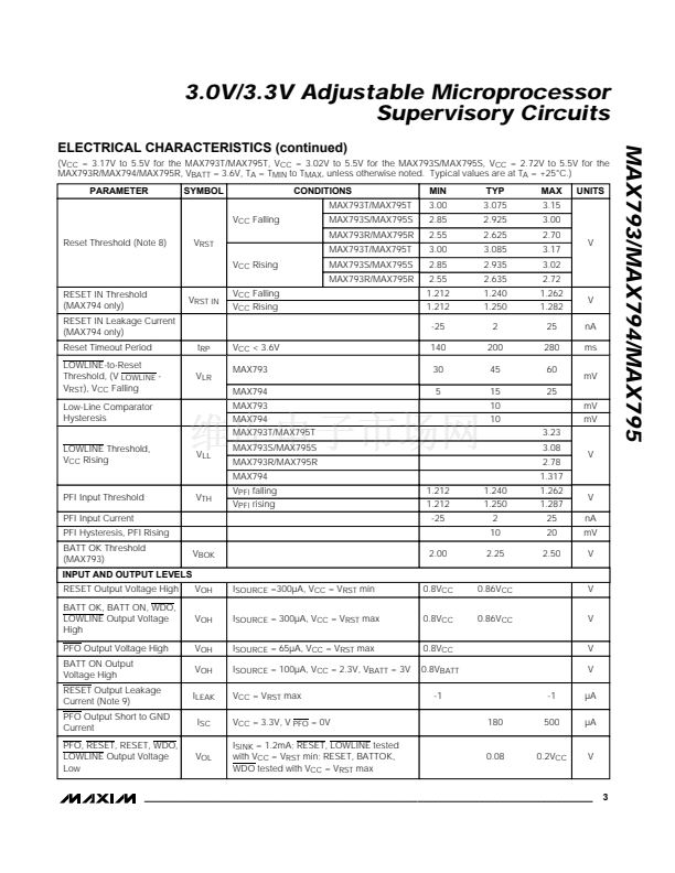
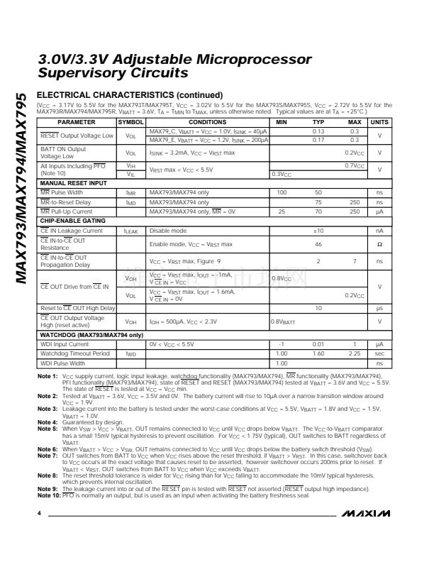
ELECTRICAL CHARACTERISTICS
(V
CC
= 3.17V to 5.5V for the MAX793T/MAX795T, V
CC
= 3.02V to 5.5V for the MAX793S/MAX795S, V
CC
= 2.72V to 5.5V for the
MAX793R/MAX794/MAX795R, V
BATT
= 3.6V, T
A
= T
MIN
to T
MAX
, unless otherwise noted. Typical values are at T
A
= +25掳C.)
PARAMETER
Operating Voltage Range,
V
CC
, V
BATT
(Note 1)
V
CC
Supply Current
(excluding I
OUT
, I
CE OUT
)
V
CC
Supply Current in
Battery-Backup Mode
(excluding I
OUT
)
BATT Supply Current
(excluding I
OUT
) (Note 2)
BATT Leakage Current,
Freshness Seal Enabled
Battery Leakage Current
(Note 3)
OUT Output Voltage in
Normal Mode
OUT Output Voltage in
Battery-Backup Mode
V
OUT
I
OUT
= 75mA
I
OUT
= 30mA (Note 4)
I
OUT
= 250碌A (Note 4)
V
BATT
= 2.3V
I
OUT
= 250碌A
I
OUT
= 1mA
V
CC
- 0.3
V
CC
- 0.12
V
CC
- 0.001
V
BATT
- 0.1
V
CC
- 0.125
V
CC
- 0.050
V
CC
- 0.5mV
V
BATT
- 0.034
V
BATT
- 0.14
20
2.69
2.55
2.30
2.82
2.68
2.41
65
2.95
2.80
2.52
V
CC
= 0V, V
OUT
= 0V
SYMBOL
MAX79_C
MAX79_E
MAX793/MAX794,
MR = V
CC
MAX795
V
CC
= 2.1V,
V
BATT
= 2.3V
V
CC
< 3.6V
V
CC
< 5.5V
V
CC
< 3.6V
V
CC
< 5.5V
MAX793/MAX794
MAX795
CONDITIONS
MIN
1.0
1.1
46
62
35
49
32
24
TYP
MAX
5.5
5.5
60
80
50
70
45
碌A
35
1
1
0.5
碌A
碌A
碌A
碌A
碌A
UNITS
V
I
SUPPLY
I
SUPPLY
V
V
OUT
V
CC
-
V
BATT
V
mV
V
SW
> V
CC
> 1.75V (Note 5)
MAX793T/MAX795T
MAX793S/MAX795S
V
BATT
> V
CC
(Note 6)
MAX793R/MAX795R/
MAX794
This value is identical to the reset threshold,
V
CC
rising for V
BATT
> V
RST
V
BATT
< V
RST
Battery Switch Threshold
(V
CC
falling)
V
SW
V
Battery Switch Threshold
(V
CC
rising) (Note 7)
V
CC
-
V
BATT
25
65
mV
2
_______________________________________________________________________________________


 1
1
 2
2
 3
3
 4
4
 5
5
 6
6
 7
7
 8
8
 9
9
 10
10
 11
11
 12
12
 13
13
 14
14
 15
15
 16
16
 17
17
 18
18
 19
19
 20
20
