MC145193
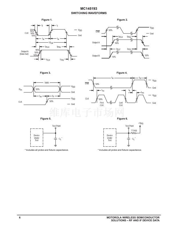
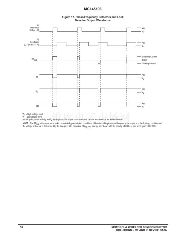
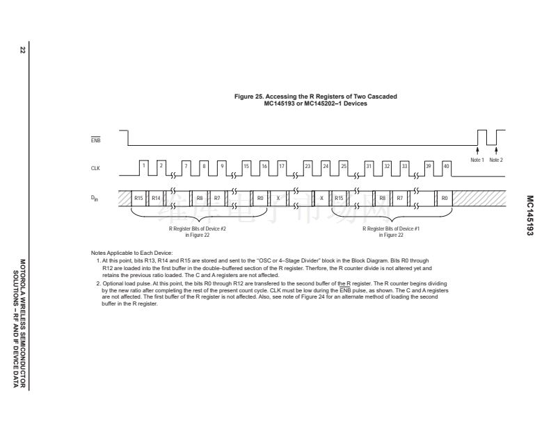
Figure 17. Phase/Frequency Detectors and Lock
Detector Output Waveforms
fR
Reference
REFin
梅
R
VH
VL
fV
Feedback
fin
梅
(N x 64 + A)
*
PDout
VH
VL
Sourcing Current
Float
Sinking Current
蠁
R
VH
VL
蠁
V
VH
VL
LD
VH = High voltage level
VL = Low voltage level
*At this point, when both fR and fV are in phase, the output source and sink circuits are turned on for a short interval.
VH
VL
NOTE:
The PDout either sources or sinks current during out鈥搊f鈥搇ock conditions. When locked in phase and frequency, the output is in the floating condition and
the voltage at that pin is determined by the low鈥損ass filter capacitor. PDout,
蠁
R, and
蠁
V are shown with the polarity bit (POL) = low; see Figure 14 for POL.
16
MOTOROLA WIRELESS SEMICONDUCTOR
SOLUTIONS 鈥?RF AND IF DEVICE DATA


 1
1
 2
2
 3
3
 4
4
 5
5
 6
6
 7
7
 8
8
 9
9
 10
10
 11
11
 12
12
 13
13
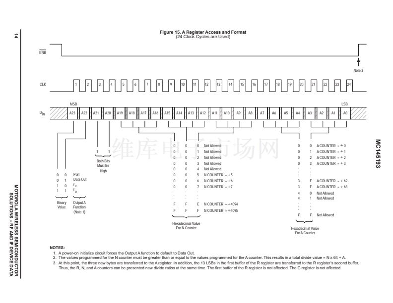 14
14
 15
15
 16
16
 17
17
 18
18
 19
19
 20
20
 21
21
 22
22
 23
23
 24
24
