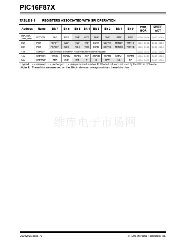
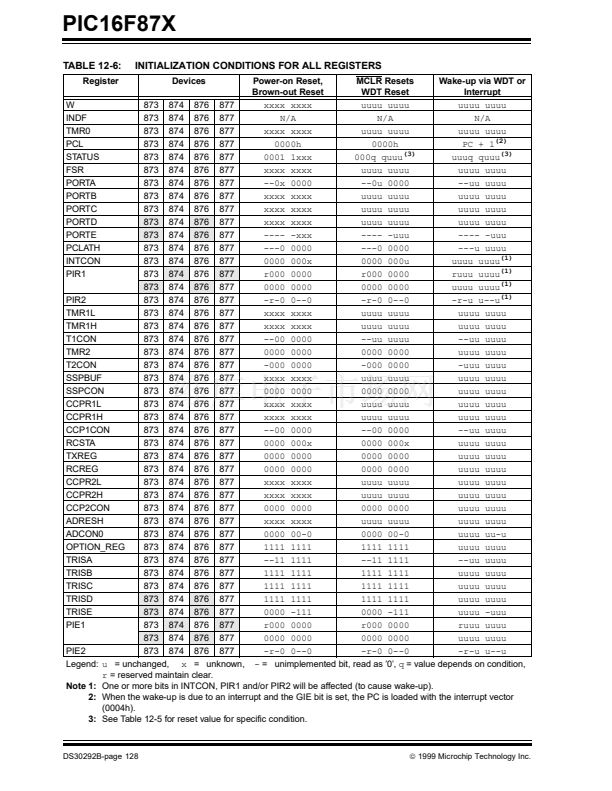
PIC16F87X
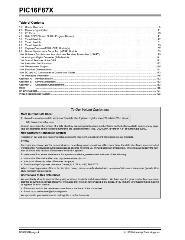
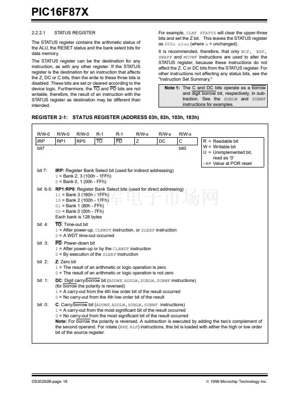
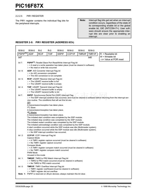
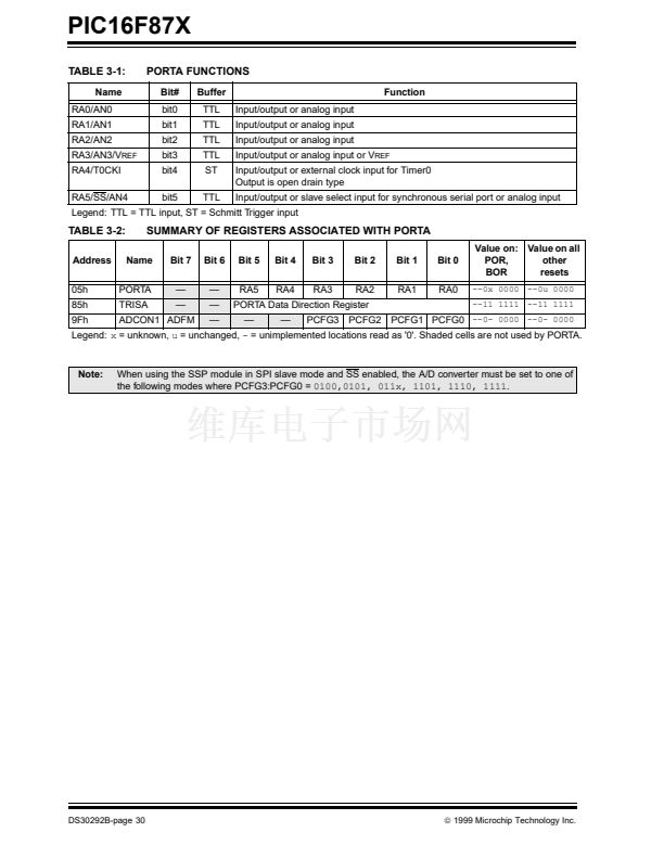
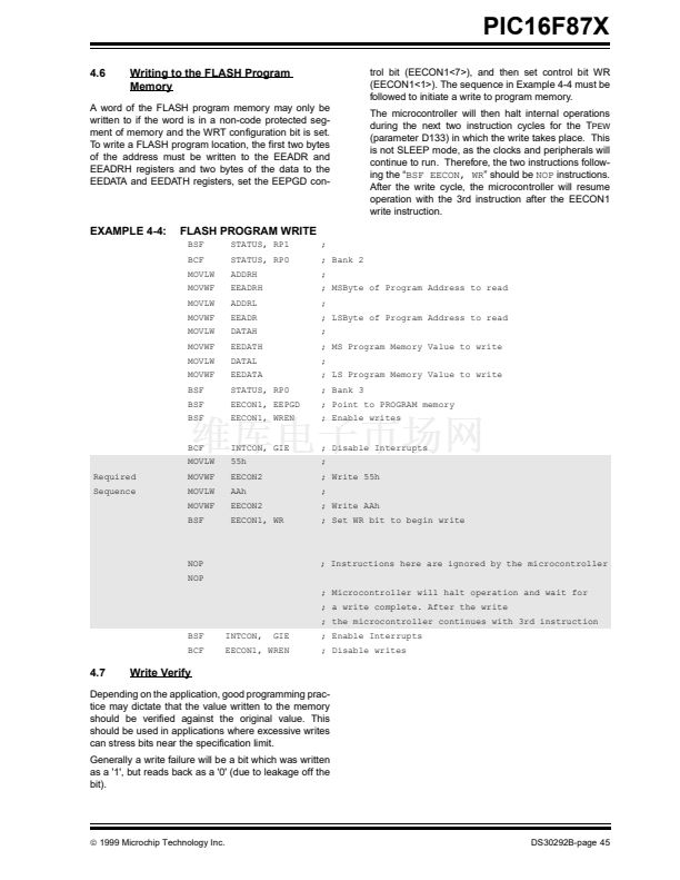
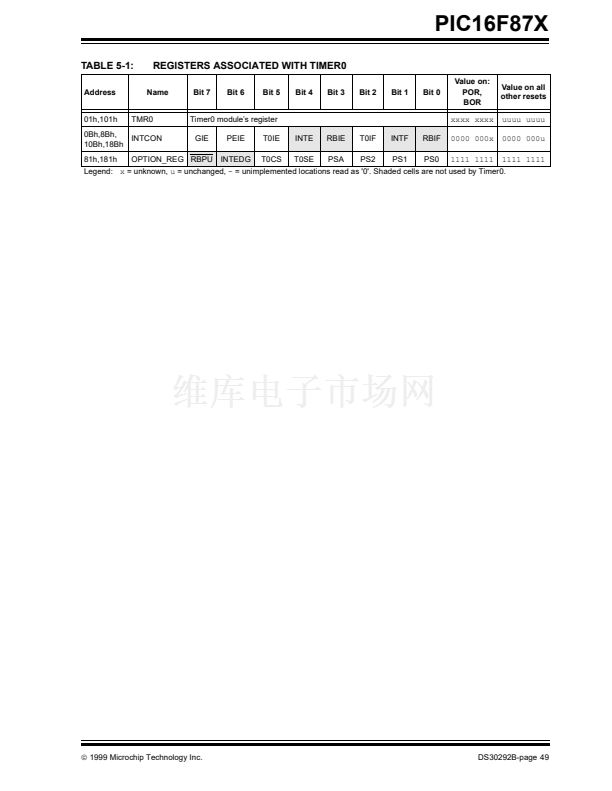
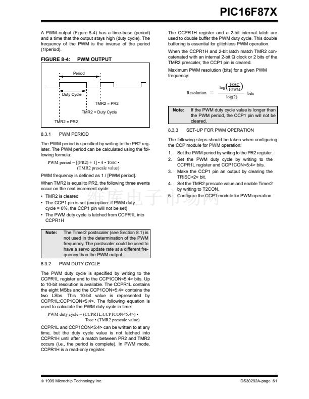
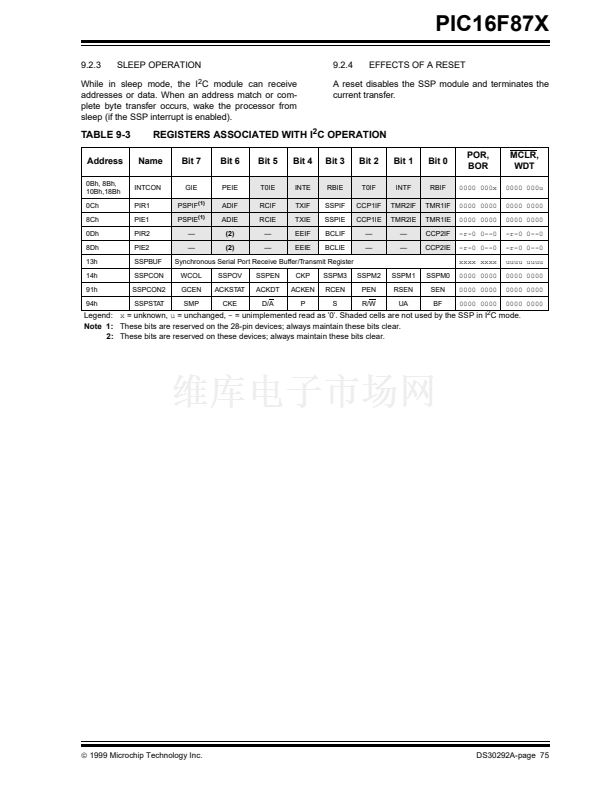
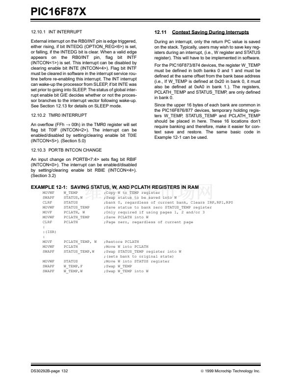
9.2.14
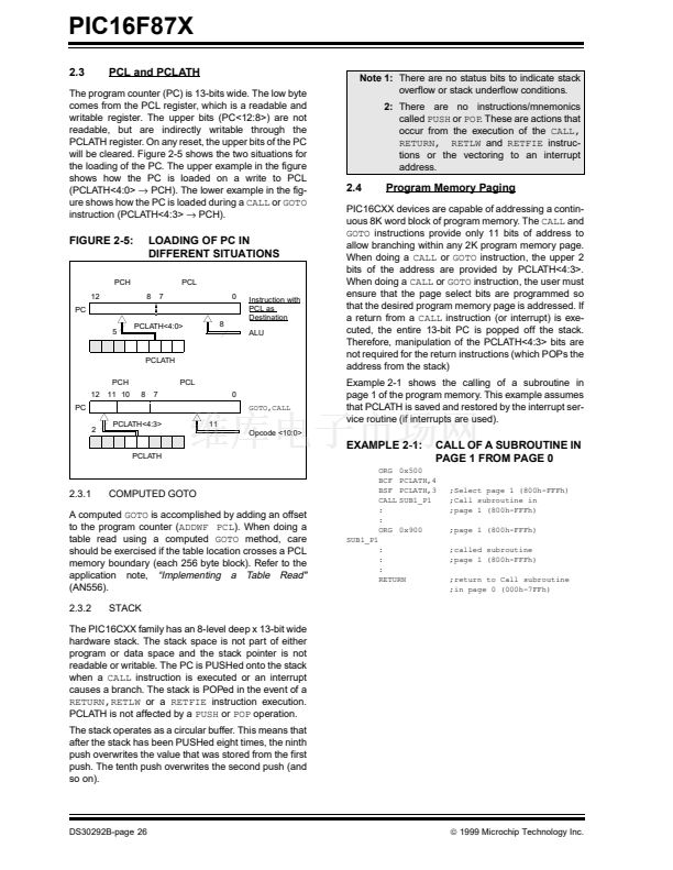
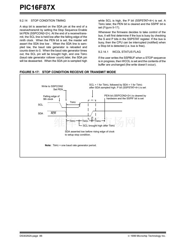
STOP CONDITION TIMING
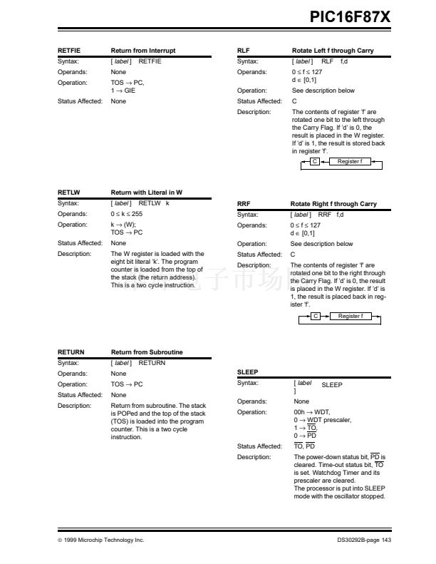
A stop bit is asserted on the SDA pin at the end of a
receive/transmit by setting the Stop Sequence Enable
bit PEN (SSPCON2<2>). At the end of a receive/trans-
mit, the SCL line is held low after the falling edge of the
ninth clock. When the PEN bit is set, the master will
assert the SDA line low . When the SDA line is sam-
pled low, the baud rate generator is reloaded and
counts down to 0. When the baud rate generator times
out, the SCL pin will be brought high, and one T
BRG
(baud rate generator rollover count) later, the SDA pin
will be deasserted. When the SDA pin is sampled high
while SCL is high, the P bit (SSPSTAT<4>) is set. A
T
BRG
later, the PEN bit is cleared and the SSPIF bit is
set (Figure
9-17).
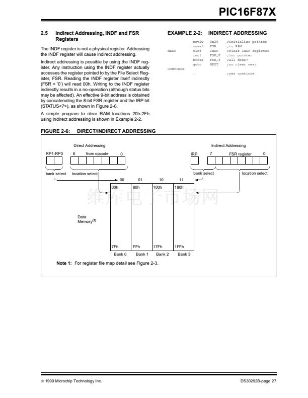
Whenever the firmware decides to take control of the
bus, it will first determine if the bus is busy by checking
the S and P bits in the SSPSTAT register. If the bus is
busy, then the CPU can be interrupted (notified) when
a Stop bit is detected (i.e. bus is free).
9.2.14.1
WCOL STATUS FLAG
If the user writes the SSPBUF when a STOP sequence
is in progress, then WCOL is set and the contents of the
buffer are unchanged (the write doesn鈥檛 occur).
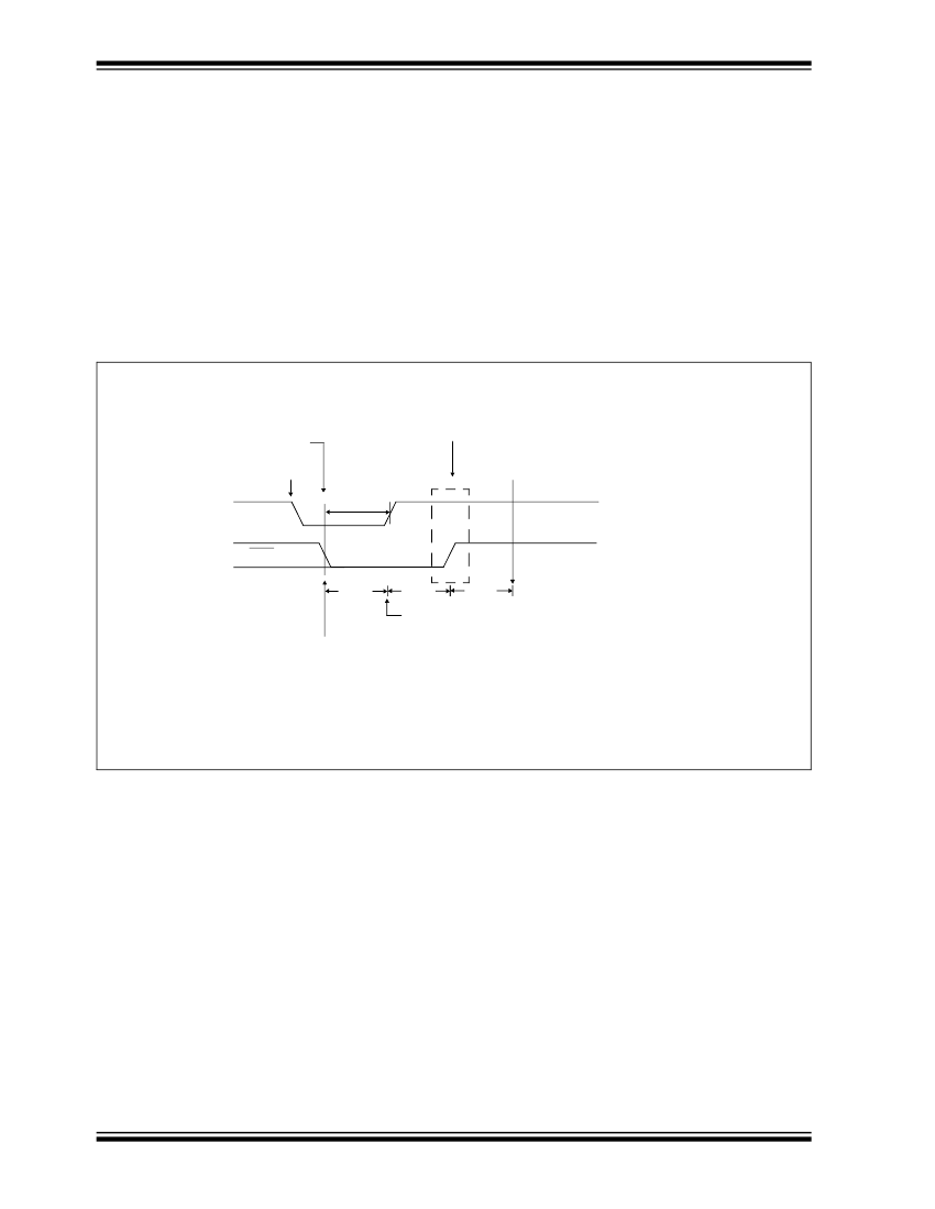
FIGURE 9-17: STOP CONDITION RECEIVE OR TRANSMIT MODE
Write to SSPCON2
Set PEN
Falling edge of
9th clock
T
BRG
SCL
SCL = 1 for T
BRG
, followed by SDA = 1 for T
BRG
after SDA sampled high. P bit (SSPSTAT<4>) is set
PEN bit (SSPCON2<2>) is cleared by
hardware and the SSPIF bit is set
SDA
ACK
P
T
BRG
T
BRG
T
BRG
SCL brought high after T
BRG
SDA asserted low before rising edge of clock
to setup stop condition.
Note:
T
BRG
= one baud rate generator period.
DS30292A-page 86
漏
1999 Microchip Technology Inc.


 1
1
 2
2
 3
3
 4
4
 5
5
 6
6
 7
7
 8
8
 9
9
 10
10
 11
11
 12
12
 13
13
 14
14
 15
15
 16
16
 17
17
 18
18
 19
19
 20
20
 21
21
 22
22
 23
23
 24
24
 25
25
 26
26
 27
27
 28
28
 29
29
 30
30
 31
31
 32
32
 33
33
 34
34
 35
35
 36
36
 37
37
 38
38
 39
39
 40
40
 41
41
 42
42
 43
43
 44
44
 45
45
 46
46
 47
47
 48
48
 49
49
 50
50
 51
51
 52
52
 53
53
 54
54
 55
55
 56
56
 57
57
 58
58
 59
59
 60
60
 61
61
 62
62
 63
63
 64
64
 65
65
 66
66
 67
67
 68
68
 69
69
 70
70
 71
71
 72
72
 73
73
 74
74
 75
75
 76
76
 77
77
 78
78
 79
79
 80
80
 81
81
 82
82
 83
83
 84
84
 85
85
 86
86
 87
87
 88
88
 89
89
 90
90
 91
91
 92
92
 93
93
 94
94
 95
95
 96
96
 97
97
 98
98
 99
99
 100
100
 101
101
 102
102
 103
103
 104
104
 105
105
 106
106
 107
107
 108
108
 109
109
 110
110
 111
111
 112
112
 113
113
 114
114
 115
115
 116
116
 117
117
 118
118
 119
119
 120
120
 121
121
 122
122
 123
123
 124
124
 125
125
 126
126
 127
127
 128
128
 129
129
 130
130
 131
131
 132
132
 133
133
 134
134
 135
135
 136
136
 137
137
 138
138
 139
139
 140
140
 141
141
 142
142
 143
143
 144
144
 145
145
 146
146
 147
147
 148
148
 149
149
 150
150
 151
151
 152
152
 153
153
 154
154
 155
155
 156
156
 157
157
 158
158
 159
159
 160
160
 161
161
 162
162
 163
163
 164
164
 165
165
 166
166
 167
167
 168
168
 169
169
 170
170
 171
171
 172
172
 173
173
 174
174
 175
175
 176
176
 177
177
 178
178
 179
179
 180
180
 181
181
 182
182
 183
183
 184
184
 185
185
 186
186
 187
187
 188
188
 189
189
 190
190
 191
191
 192
192
 193
193
 194
194
 195
195
 196
196
 197
197
 198
198
 199
199
 200
200
