鈥?/div>
Baud Rate Generator
Sampling Circuit
Asynchronous Transmitter
Asynchronous Receiver
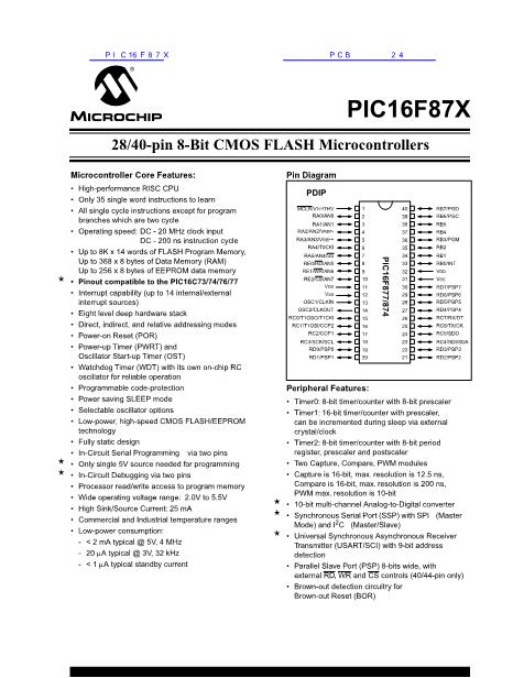
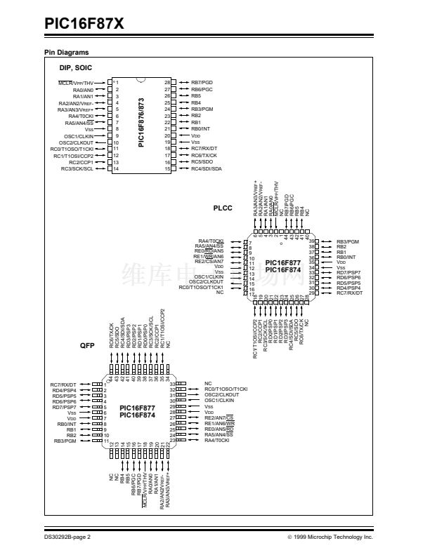
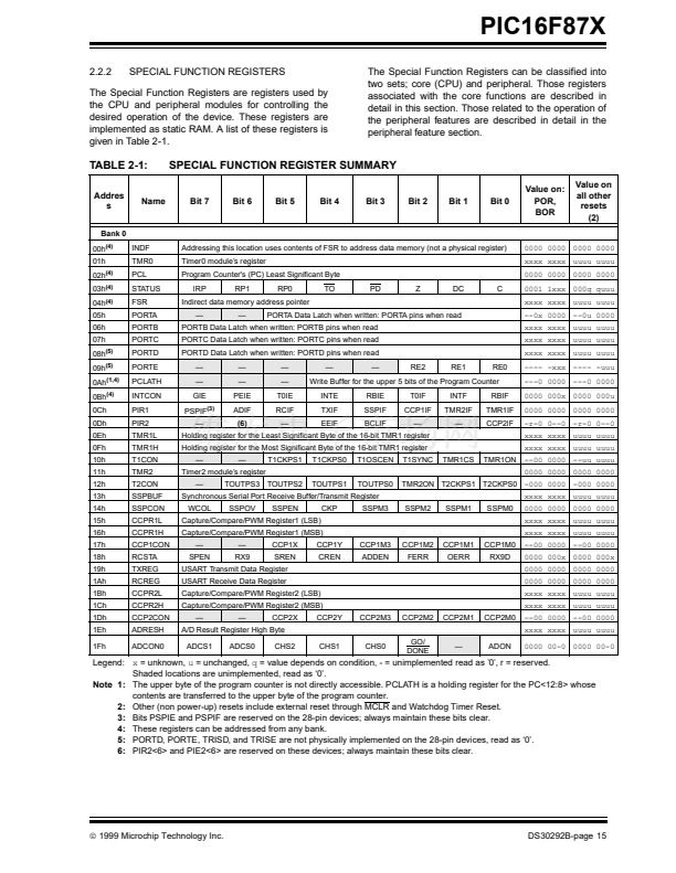
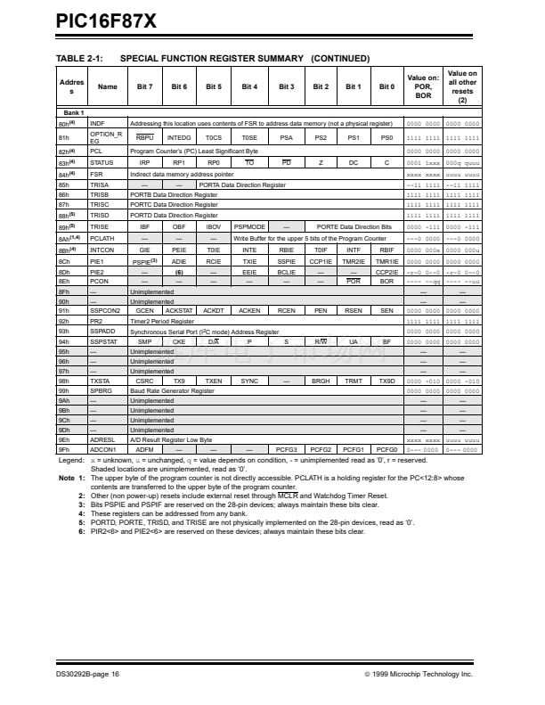
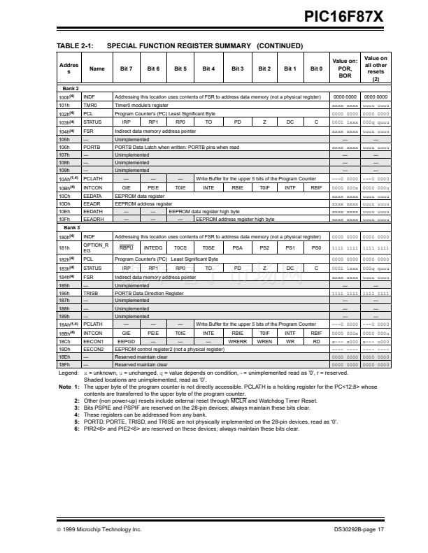
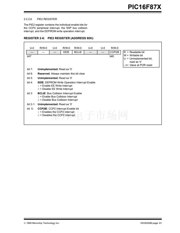
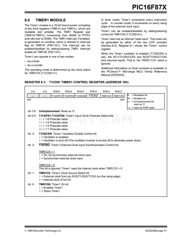
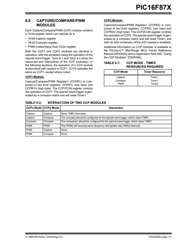
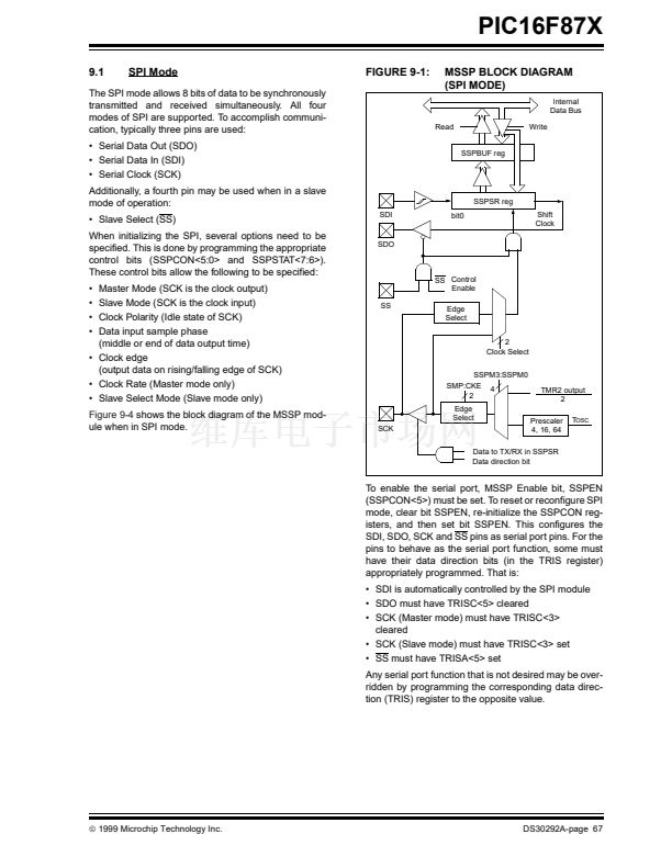
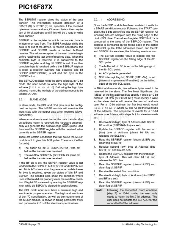
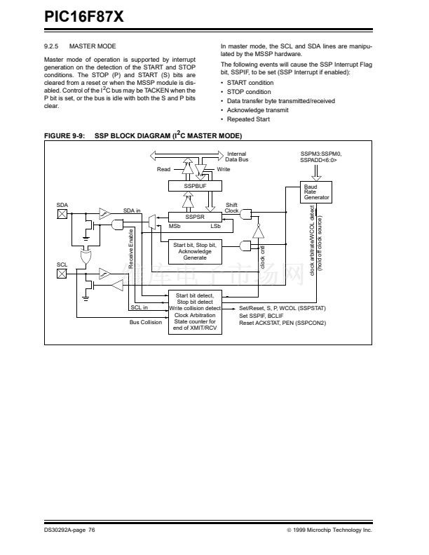
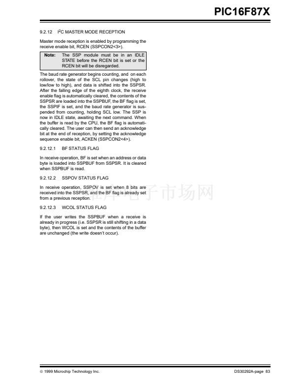
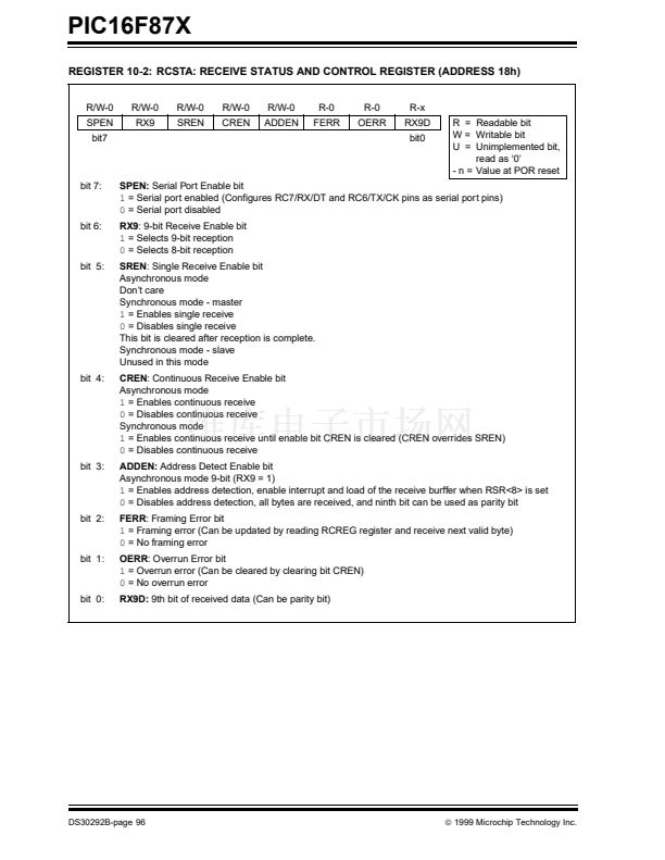
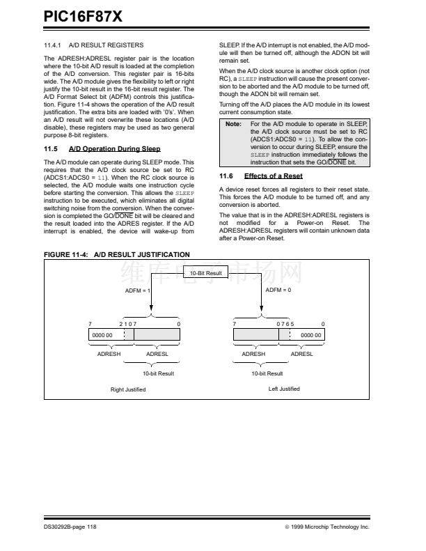
USART ASYNCHRONOUS TRANSMITTER
( PIE1<4>). Flag bit TXIF will be set, regardless of the
state of enable bit TXIE and cannot be cleared in soft-
ware. It will reset only when new data is loaded into the
TXREG register. While flag bit TXIF indicates the status
of the TXREG register, another bit TRMT (TXSTA<1>)
shows the status of the TSR register. Status bit TRMT
is a read only bit, which is set when the TSR register is
empty. No interrupt logic is tied to this bit, so the user
has to poll this bit in order to determine if the TSR reg-
ister is empty.
Note 1:
The TSR register is not mapped in data
memory, so it is not available to the user.
2:
Flag bit TXIF is set when enable bit TXEN
is set. TXIF is cleared by loading TXREG.
Transmission is enabled by setting enable bit TXEN
(TXSTA<5>). The actual transmission will not occur
until the TXREG register has been loaded with data
and the baud rate generator (BRG) has produced a
shift clock (Figure 10-2). The transmission can also be
started by first loading the TXREG register and then
setting enable bit TXEN. Normally, when transmission
is first started, the TSR register is empty. At that point,
transfer to the TXREG register will result in an immedi-
ate transfer to TSR, resulting in an empty TXREG. A
back-to-back transfer is thus possible (Figure 10-3).
Clearing enable bit TXEN during a transmission will
cause the transmission to be aborted and will reset the
transmitter. As a result, the RC6/TX/CK pin will revert
to hi-impedance.
In order to select 9-bit transmission, transmit bit TX9
(TXSTA<6>) should be set and the ninth bit should be
written to TX9D (TXSTA<0>). The ninth bit must be
written before writing the 8-bit data to the TXREG reg-
ister. This is because a data write to the TXREG regis-
ter can result in an immediate transfer of the data to the
TSR register (if the TSR is empty). In such a case, an
incorrect ninth data bit may be loaded in the TSR
register.
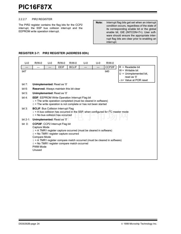
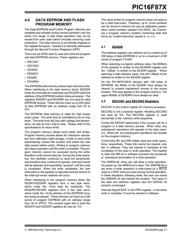
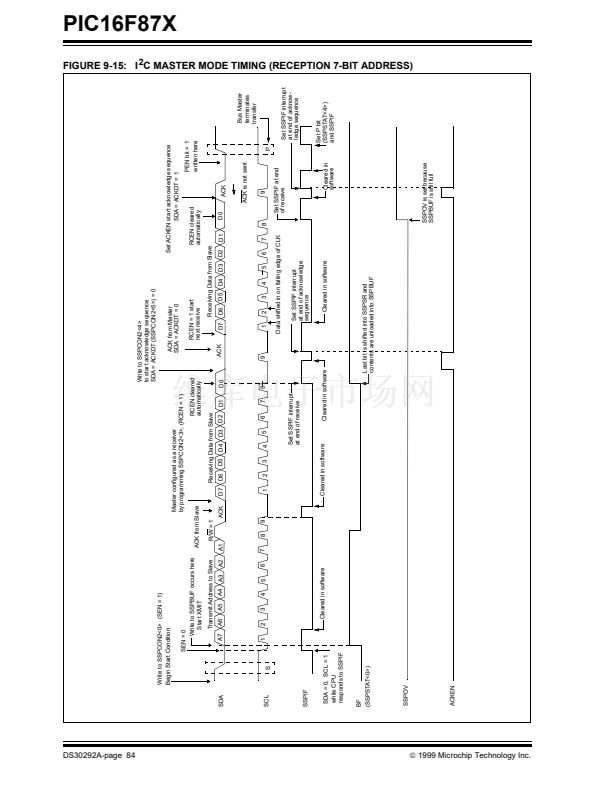
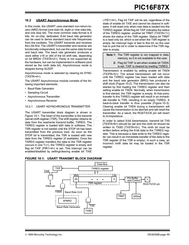
10.2.1
The USART transmitter block diagram is shown in
Figure 10-1. The heart of the transmitter is the transmit
(serial) shift register (TSR). The shift register obtains its
data from the read/write transmit buffer, TXREG. The
TXREG register is loaded with data in software. The
TSR register is not loaded until the STOP bit has been
transmitted from the previous load. As soon as the
STOP bit is transmitted, the TSR is loaded with new
data from the TXREG register (if available). Once the
TXREG register transfers the data to the TSR register
(occurs in one T
CY
), the TXREG register is empty and
flag bit TXIF (PIR1<4>) is set. This interrupt can be
enabled/disabled by setting/clearing enable bit TXIE
FIGURE 10-1: USART TRANSMIT BLOCK DIAGRAM
Data Bus
TXIF
TXIE
MSb
(8)
Interrupt
TXEN
Baud Rate CLK
TRMT
SPBRG
Baud Rate Generator
TX9
TX9D
SPEN
TXREG register
8
鈥?鈥?鈥?/div>
TSR register
LSb
0
Pin Buffer
and Control
RC6/TX/CK pin
漏
1999 Microchip Technology Inc.
DS30292B-page 99


 1
1
 2
2
 3
3
 4
4
 5
5
 6
6
 7
7
 8
8
 9
9
 10
10
 11
11
 12
12
 13
13
 14
14
 15
15
 16
16
 17
17
 18
18
 19
19
 20
20
 21
21
 22
22
 23
23
 24
24
 25
25
 26
26
 27
27
 28
28
 29
29
 30
30
 31
31
 32
32
 33
33
 34
34
 35
35
 36
36
 37
37
 38
38
 39
39
 40
40
 41
41
 42
42
 43
43
 44
44
 45
45
 46
46
 47
47
 48
48
 49
49
 50
50
 51
51
 52
52
 53
53
 54
54
 55
55
 56
56
 57
57
 58
58
 59
59
 60
60
 61
61
 62
62
 63
63
 64
64
 65
65
 66
66
 67
67
 68
68
 69
69
 70
70
 71
71
 72
72
 73
73
 74
74
 75
75
 76
76
 77
77
 78
78
 79
79
 80
80
 81
81
 82
82
 83
83
 84
84
 85
85
 86
86
 87
87
 88
88
 89
89
 90
90
 91
91
 92
92
 93
93
 94
94
 95
95
 96
96
 97
97
 98
98
 99
99
 100
100
 101
101
 102
102
 103
103
 104
104
 105
105
 106
106
 107
107
 108
108
 109
109
 110
110
 111
111
 112
112
 113
113
 114
114
 115
115
 116
116
 117
117
 118
118
 119
119
 120
120
 121
121
 122
122
 123
123
 124
124
 125
125
 126
126
 127
127
 128
128
 129
129
 130
130
 131
131
 132
132
 133
133
 134
134
 135
135
 136
136
 137
137
 138
138
 139
139
 140
140
 141
141
 142
142
 143
143
 144
144
 145
145
 146
146
 147
147
 148
148
 149
149
 150
150
 151
151
 152
152
 153
153
 154
154
 155
155
 156
156
 157
157
 158
158
 159
159
 160
160
 161
161
 162
162
 163
163
 164
164
 165
165
 166
166
 167
167
 168
168
 169
169
 170
170
 171
171
 172
172
 173
173
 174
174
 175
175
 176
176
 177
177
 178
178
 179
179
 180
180
 181
181
 182
182
 183
183
 184
184
 185
185
 186
186
 187
187
 188
188
 189
189
 190
190
 191
191
 192
192
 193
193
 194
194
 195
195
 196
196
 197
197
 198
198
 199
199
 200
200
