mode. See
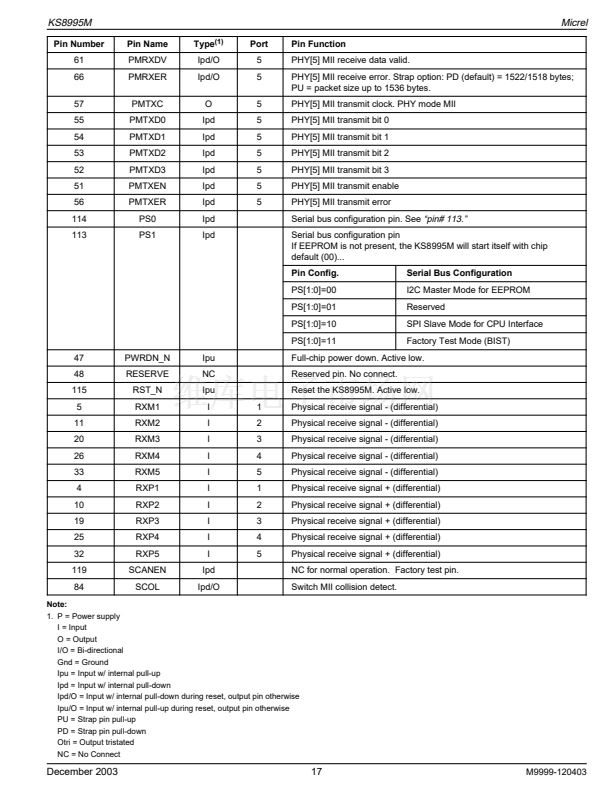
鈥減in# 113.鈥?/div>
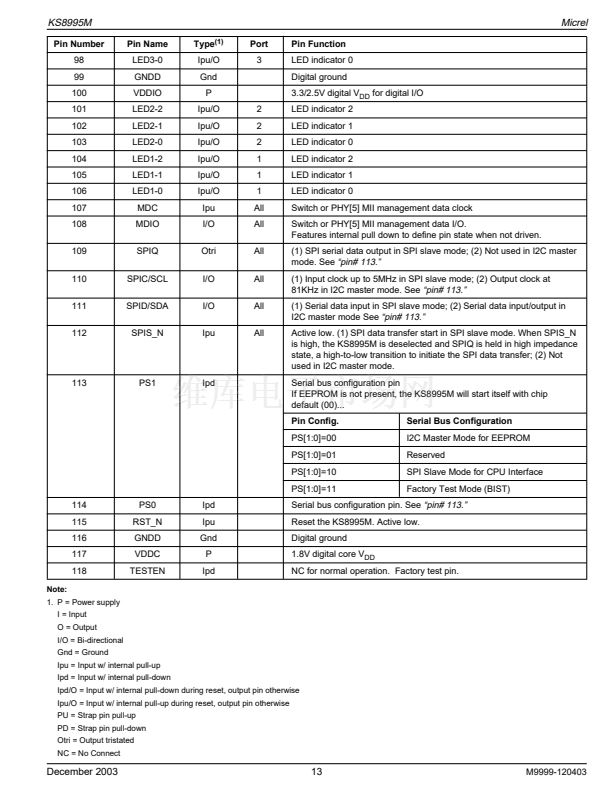
Active low. (1) SPI data transfer start in SPI slave mode. When SPIS_N
is high, the KS8995M is deselected and SPIQ is held in high impedance
state, a high-to-low transition to initiate the SPI data transfer; (2) Not
used in I2C master mode.
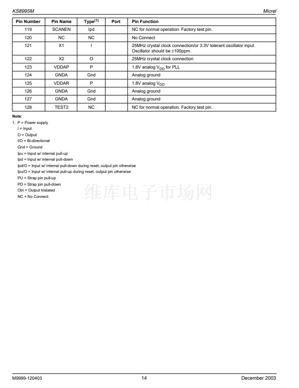
No connect for normal operation. Factory test pin.
No Connect for normal operation. Factory test pin.
128
118
8
14
23
29
36
7
13
22
28
35
123
41
43
3
15
31
125
18
9
24
37
50
Note:
1. P = Power supply
I = Input
O = Output
I/O = Bi-directional
TEST2
TESTEN
TXP1
TXP2
TXP3
TXP4
TXP5
TXM1
TXM2
TXM3
TXM4
TXM5
VDDAP
VDDAR
VDDAR
VDDAR
VDDAR
VDDAR
VDDAR
VDDAT
VDDAT
VDDAT
VDDAT
VDDC
NC
Ipd
O
O
O
O
O
O
O
O
O
O
P
P
P
P
P
P
P
P
P
P
P
P
1
2
3
4
5
1
2
3
4
5
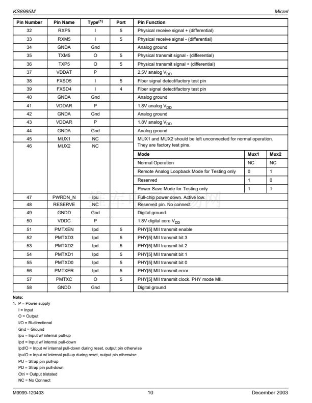
Physical transmit signal + (differential)
Physical transmit signal + (differential)
Physical transmit signal + (differential)
Physical transmit signal + (differential)
Physical transmit signal + (differential)
Physical transmit signal - (differential)
Physical transmit signal - (differential)
Physical transmit signal - (differential)
Physical transmit signal - (differential)
Physical transmit signal - (differential)
1.8V analog V
DD
for PLL
1.8V analog V
DD
1.8V analog V
DD
1.8V analog V
DD
1.8V analog V
DD
1.8V analog V
DD
1.8V analog V
DD
2.5V analog V
DD
2.5V analog V
DD
2.5V analog V
DD
2.5V analog V
DD
1.8V digital core V
DD
Gnd = Ground
Ipu = Input w/ internal pull-up
Ipd = Input w/ internal pull-down
Ipd/O = Input w/ internal pull-down during reset, output pin otherwise
Ipu/O = Input w/ internal pull-up during reset, output pin otherwise
PU = Strap pin pull-up
PD = Strap pin pull-down
Otri = Output tristated
NC = No Connect
December 2003
19
M9999-120403


 1
1
 2
2
 3
3
 4
4
 5
5
 6
6
 7
7
 8
8
 9
9
 10
10
 11
11
 12
12
 13
13
 14
14
 15
15
 16
16
 17
17
 18
18
 19
19
 20
20
 21
21
 22
22
 23
23
 24
24
 25
25
 26
26
 27
27
 28
28
 29
29
 30
30
 31
31
 32
32
 33
33
 34
34
 35
35
 36
36
 37
37
 38
38
 39
39
 40
40
 41
41
 42
42
 43
43
 44
44
 45
45
 46
46
 47
47
 48
48
 49
49
 50
50
 51
51
 52
52
 53
53
 54
54
 55
55
 56
56
 57
57
 58
58
 59
59
 60
60
 61
61
 62
62
 63
63
 64
64
 65
65
 66
66
 67
67
 68
68
 69
69
 70
70
 71
71
 72
72
 73
73
