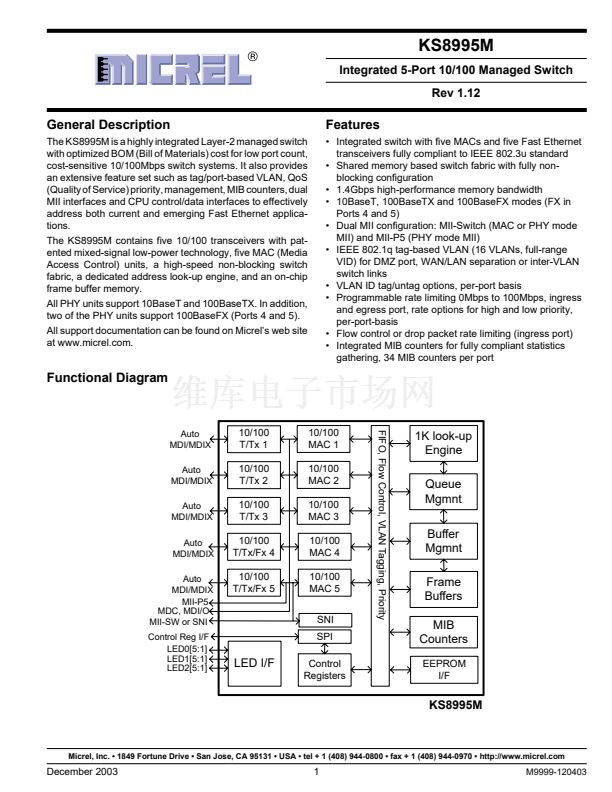
KS8995M
Micrel
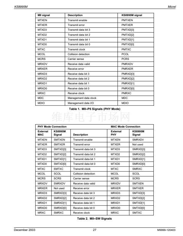
The MII-P5 interface operates in PHY mode only, while the MII-SW interface operates in either MAC mode or PHY mode. These
interfaces are nibble wide data interfaces and therefore run at 1/4 the network bit rate (not encoded). Additional signals on the
transmit side indicate when data is valid or when an error occurs during transmission. Likewise, the receive side has indicators
that convey when the data is valid and without physical layer errors. For half-duplex operation there is a signal that indicates
a collision has occurred during transmission.
Note that the signal MRXER is not provided on the MII-SW interface for PHY mode operation and the signal MTXER is not
provided on the MII-SW interface for MAC mode operation. Normally MRXER would indicate a receive error coming from the
physical layer device. MTXER would indicate a transmit error from the MAC device. These signals are not appropriate for this
configuration. For PHY mode operation, if the device interfacing with the KS8995M has an MRXER pin, it should be tied low.
For MAC mode operation, if the device interfacing with the KS8995M has an MTXER pin, it should be tied low.
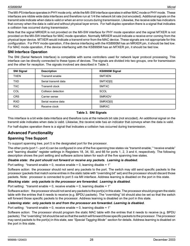
SNI Interface Operation
The SNI (Serial Network Interface) is compatible with some controllers used for network layer protocol processing. This
interface can be directly connected to these types of devices. The signals are divided into two groups, one for transmission
and the other for reception. The signals involved are described in Table 3.
SNI Signal
TXEN
TXD
TXC
COL
CRS
RXD
RXC
Description
Transmit enable
Serial transmit data
Transmit clock
Collision detection
Carrier sense
Serial receive data
Receive clock
KS8995M Signal
SMTXEN
SMTXD[0]
SMTXC
SCOL
SMRXDV
SMRXD[0]
SMRXC
Table 3. SNI Signals
This interface is a bit wide data interface and therefore runs at the network bit rate (not encoded). An additional signal on the
transmit side indicates when data is valid. Likewise, the receive side has an indicator that conveys when the data is valid.
For half-duplex operation there is a signal that indicates a collision has occurred during transmission.
Advanced Functionality
Spanning Tree Support
To support spanning tree, port 5 is the designated port for the processor.
The other ports (port 1 - port 4) can be configured in one of the five spanning tree states via 鈥渢ransmit enable,鈥?鈥渞eceive enable鈥?/div>
and 鈥渓earning disable鈥?register settings in Registers 18, 34, 50, and 66 for ports 1, 2, 3 and 4, respectively. The following
description shows the port setting and software actions taken for each of the five spanning tree states.
Disable state: the port should not forward or receive any packets. Learning is disabled.
Port setting: 鈥渢ransmit enable = 0, receive enable = 0, learning disable = 1鈥?/div>
Software action: the processor should not send any packets to the port. The switch may still send specific packets to the
processor (packets that match some entries in the static table with 鈥渙verriding bit鈥?set) and the processor should discard those
packets. Note: processor is connected to port 5 via MII interface. Address learning is disabled on the port in this state.
Blocking state: only packets to the processor are forwarded. Learning is disabled.
Port setting: 鈥渢ransmit enable = 0, receive enable = 0, learning disable = 1鈥?/div>
Software action: the processor should not send any packets to the port(s) in this state. The processor should program the static
table with the entries that it needs to receive (e.g. BPDU packets). The 鈥渙verriding鈥?bit should also be set so that the switch
will forward those specific packets to the processor. Address learning is disabled on the port in this state.
Listening state: only packets to and from the processor are forwarded. Learning is disabled.
Port setting: 鈥渢ransmit enable = 0, receive enable = 0, learning disable = 1鈥?/div>
Software action: The processor should program the static MAC table with the entries that it needs to receive (e.g. BPDU
packets). The 鈥渙verriding鈥?bit should be set so that the switch will forward those specific packets to the processor. The processor
may send packets to the port(s) in this state, see
鈥淪pecial Tagging Mode鈥?/div>
section for details. Address learning is disabled on
the port in this state.
M9999-120403
28
December 2003
KS8995MI 产品属性
66
集成电路 (IC)
专用 IC
*
*
*
表面贴装
128-BFQFP
128-PQFP(14x20)
散装
576-1020
KS8995MI相关型号PDF文件下载
-
型号
版本
描述
厂商
下载
-
英文版
3-Port 10/100 Integrated Switch with PHY and Frame Buffer
-
英文版
Telecomm/Datacomm, Other - Datasheet Reference
-
英文版
5 Port 10/100 Switch with PHY
ETC
-
英文版
5 Port 10/100 Switch with PHY
ETC [ETC]
-
英文版
Micrel Semiconductor [8-Port 10/100 Integrated Switch with ...
-
英文版
Micrel Semiconductor [Integrated 9-Port 10/100 Switch with ...
-
英文版
Micrel Semiconductor [3-Port 10/100 Integrated Switch with ...
-
英文版
Micrel Semiconductor [Integrated 3-Port 10/100 Managed Inte...
-
英文版
5 Port 10/100 Switch with PHY. Buffers. QoS
-
英文版
5 Port 10/100 Switch with PHY
ETC
-
英文版
Integrated 5-Port 10/100 Managed Switch
-
英文版
5 Port 10/100 Switch with PHY
ETC [ETC]
-
英文版
Integrated 5-Port 10/100 QoS Switch
-
英文版
Integrated 5-Port 10/100 QoS Switch
MICREL [Mi...
-
英文版
Integrated 9-Port 10/100 Switch with PHY and Frame Buffer
-
英文版
IC CONV MED 10/100 SGL 128PQFP
-
英文版
Integrated 3-Port 10/100 Managed Integrated 3-Port 10/100 Ma...
-
英文版
Integrated 3-Port 10/100 Managed Integrated 3-Port 10/100 Ma...
-
英文版
Integrated 5-Port 10/100 Managed Switch
-
英文版
Integrated 5-Port 10/100 Managed Switch
MICREL [Mi...


 1
1
 2
2
 3
3
 4
4
 5
5
 6
6
 7
7
 8
8
 9
9
 10
10
 11
11
 12
12
 13
13
 14
14
 15
15
 16
16
 17
17
 18
18
 19
19
 20
20
 21
21
 22
22
 23
23
 24
24
 25
25
 26
26
 27
27
 28
28
 29
29
 30
30
 31
31
 32
32
 33
33
 34
34
 35
35
 36
36
 37
37
 38
38
 39
39
 40
40
 41
41
 42
42
 43
43
 44
44
 45
45
 46
46
 47
47
 48
48
 49
49
 50
50
 51
51
 52
52
 53
53
 54
54
 55
55
 56
56
 57
57
 58
58
 59
59
 60
60
 61
61
 62
62
 63
63
 64
64
 65
65
 66
66
 67
67
 68
68
 69
69
 70
70
 71
71
 72
72
 73
73
