KS8995M
Micrel
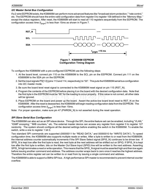
Introduction
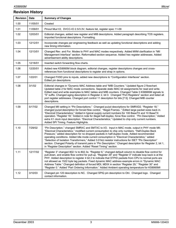
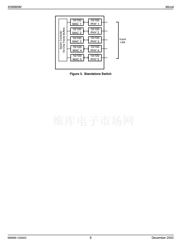
The KS8995M contains five 10/100 physical layer transceivers and five MAC (Media Access Control) units with an integrated
layer 2 managed switch. The device runs in three modes. The first mode is as a five-port integrated switch. The second is as
a five-port switch with the fifth port decoupled from the physical port. In this mode access to the fifth MAC is provided through
an MII (Media Independent Interface). This is useful for implementing an integrated broadband router. The third mode uses
the dual MII feature to recover the use of the fifth PHY. This allows the additional broadband gateway configuration, where the
fifth PHY may be accessed through the MII-P5 port.
The KS8995M has the flexibility to reside in a managed or unmanaged design. In a managed design, a host processor has
complete control of the KS8995M via the SPI bus, or partial control via the MDC/MDIO interface. An unmanaged design is
achieved through I/O strapping or EEPROM programming at system reset time.
On the media side, the KS8995M supports IEEE 802.3 10BaseT, 100BaseTX on all ports, and 100BaseFX on ports 4 and 5.
The KS8995M can be used as two separate media converters.
Physical signal transmission and reception are enhanced through the use of patented analog circuitry that makes the design
more efficient and allows for lower power consumption and smaller chip die size.
The major enhancements from the KS8995E to the KS8995M are support for host processor management, a dual MII interface,
tag as well as port based VLAN, spanning tree protocol support, IGMP snooping support, port mirroring support and rate limiting
functionality.
Functional Overview: Physical Layer Transceiver
100BaseTX Transmit
The 100BaseTX transmit function performs parallel to serial conversion, 4B/5B coding, scrambling, NRZ-to-NRZI conversion,
MLT3 encoding and transmission. The circuit starts with a parallel-to-serial conversion, which converts the MII data from the
MAC into a 125MHz serial bit stream. The data and control stream is then converted into 4B/5B coding followed by a scrambler.
The serialized data is further converted from NRZ to NRZI format, and then transmitted in MLT3 current output. The output
current is set by an external 1% 3.01k鈩?resistor for the 1:1 transformer ratio. It has a typical rise/fall time of 4ns and complies
with the ANSI TP-PMD standard regarding amplitude balance, overshoot and timing jitter. The wave-shaped 10BaseT output
is also incorporated into the 100BaseTX transmitter.
100BaseTX Receive
The 100BaseTX receiver function performs adaptive equalization, DC restoration, MLT3-to-NRZI conversion, data and clock
recovery, NRZI-to-NRZ conversion, de-scrambling, 4B/5B decoding and serial-to-parallel conversion. The receiving side
starts with the equalization filter to compensate for inter-symbol interference (ISI) over the twisted pair cable. Since the
amplitude loss and phase distortion is a function of the length of the cable, the equalizer has to adjust its characteristics to
optimize the performance. In this design, the variable equalizer will make an initial estimation based on comparisons of
incoming signal strength against some known cable characteristics, it then tunes itself for optimization. This is an ongoing
process and can self-adjust against environmental changes such as temperature variations.
The equalized signal then goes through a DC restoration and data conversion block. The DC restoration circuit is used to
compensate for the effect of baseline wander and improve the dynamic range. The differential data conversion circuit converts
the MLT3 format back to NRZI. The slicing threshold is also adaptive.
The clock recovery circuit extracts the 125MHz clock from the edges of the NRZI signal. This recovered clock is then used to
convert the NRZI signal into the NRZ format. The signal is then sent through the de-scrambler followed by the 4B/5B decoder.
Finally, the NRZ serial data is converted to the MII format and provided as the input data to the MAC.
PLL Clock Synthesizer
The KS8995M generates 125MHz, 42MHz, 25MHz and 10MHz clocks for system timing. Internal clocks are generated from
an external 25MHz crystal or oscillator.
Scrambler/De-scrambler (100BaseTX only)
The purpose of the scrambler is to spread the power spectrum of the signal in order to reduce EMI and baseline wander. The
data is scrambled through the use of an 11-bit wide linear feedback shift register (LFSR). This can generate a 2047-bit non-
repetitive sequence. The receiver will then de-scramble the incoming data stream with the same sequence at the transmitter.
100BaseFX Operation
100BaseFX operation is very similar to 100BaseTX operation except that the scrambler/de-scrambler and MLT3 encoder/
decoder are bypassed on transmission and reception. In this mode the auto-negotiation feature is bypassed since there is no
standard that supports fiber auto-negotiation.
100BaseFX Signal Detection
The physical port runs in 100BaseFX mode if FXSDx >0.6V for ports 4 and 5 only. This signal is internally referenced to 1.25V.
The fiber module interface should be set by a voltage divider such that FXSDx 鈥楬鈥?is above this 1.25V reference, indicating signal
M9999-120403
22
December 2003


 1
1
 2
2
 3
3
 4
4
 5
5
 6
6
 7
7
 8
8
 9
9
 10
10
 11
11
 12
12
 13
13
 14
14
 15
15
 16
16
 17
17
 18
18
 19
19
 20
20
 21
21
 22
22
 23
23
 24
24
 25
25
 26
26
 27
27
 28
28
 29
29
 30
30
 31
31
 32
32
 33
33
 34
34
 35
35
 36
36
 37
37
 38
38
 39
39
 40
40
 41
41
 42
42
 43
43
 44
44
 45
45
 46
46
 47
47
 48
48
 49
49
 50
50
 51
51
 52
52
 53
53
 54
54
 55
55
 56
56
 57
57
 58
58
 59
59
 60
60
 61
61
 62
62
 63
63
 64
64
 65
65
 66
66
 67
67
 68
68
 69
69
 70
70
 71
71
 72
72
 73
73
