Freescale Semiconductor, Inc.
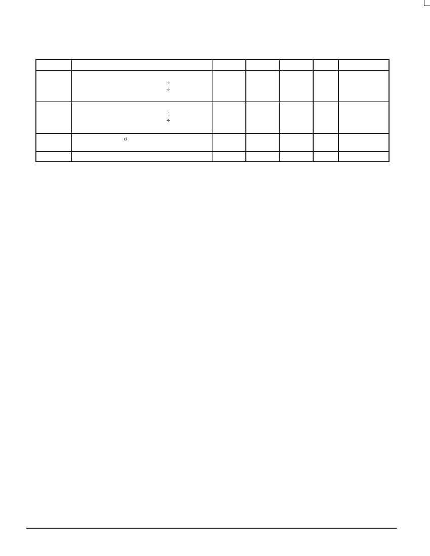
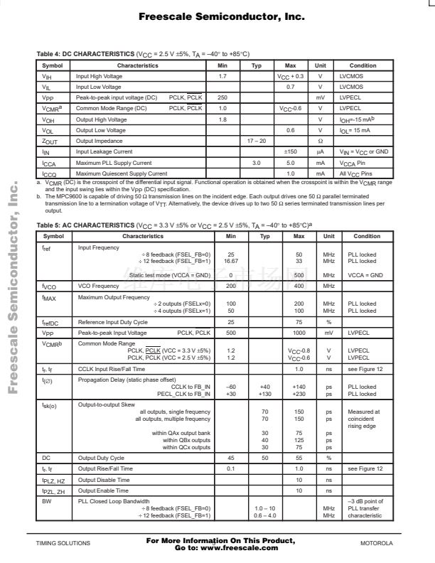
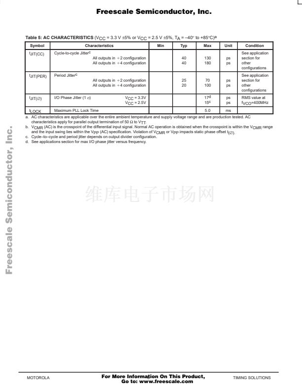
Table 5: AC CHARACTERISTICS
(VCC = 3.3 V
卤5%
or VCC = 2.5 V
卤5%,
TA = 鈥?0掳 to +85掳C)
a
Symbol
tJIT(CC)
Characteristics
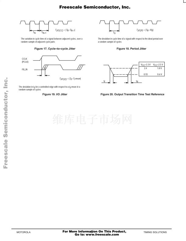
Cycle-to-cycle Jitterc
All outputs in
All outputs in
tJIT(PER)
Period Jitterc
All outputs in
All outputs in
tJIT(鈭?
I/O Phase Jitter (1
s
)
Min
Typ
40
40
Max
130
180
Unit
ps
ps
Condition
See application
section for
other
configurations
See application
section for
other
configurations
RMS value at
fVCO=400MHz
B
2 configuration
B
4 configuration
B
2 configuration
B
4 configuration
VCC = 3.3V
VCC = 2.5V
25
20
70
100
17d
15c
ps
ps
ps
ps
Freescale Semiconductor, Inc...
tLOCK
Maximum PLL Lock Time
5.0
ms
a. AC characteristics are applicable over the entire ambient temperature and supply voltage range and are production tested. AC
characteristics apply for parallel output termination of 50
鈩?/div>
to VTT.
b. VCMR (AC) is the crosspoint of the differential input signal. Normal AC operation is obtained when the crosspoint is within the VCMR range
and the input swing lies within the VPP (AC) specification. Violation of VCMR or VPP impacts static phase offset t(鈭?.
c. Cycle鈥搕o鈥揷ycle and period jitter depends on output divider configuration.
d. See applications section for max I/O phase jitter versus frequency.
MOTOROLA
For More Information On This Product,
6
Go to: www.freescale.com
TIMING SOLUTIONS


 1
1
 2
2
 3
3
 4
4
 5
5
 6
6
 7
7
 8
8
 9
9
 10
10
 11
11
 12
12
 13
13
 14
14
 15
15
 16
16
