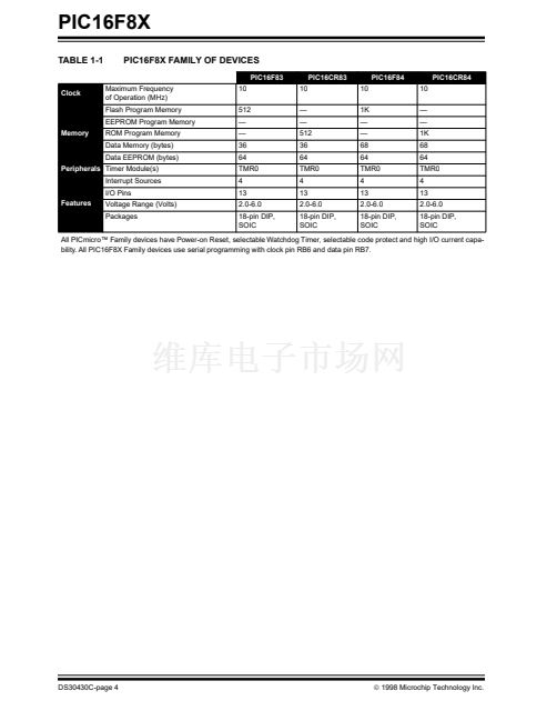
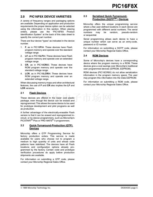
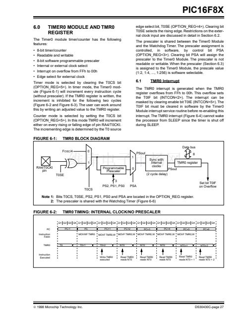
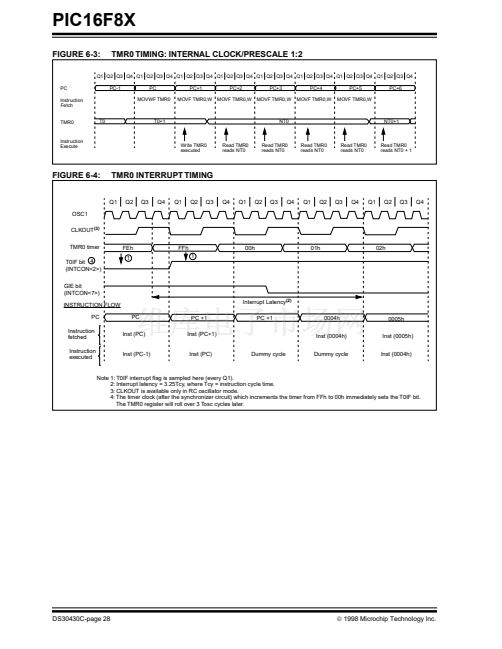
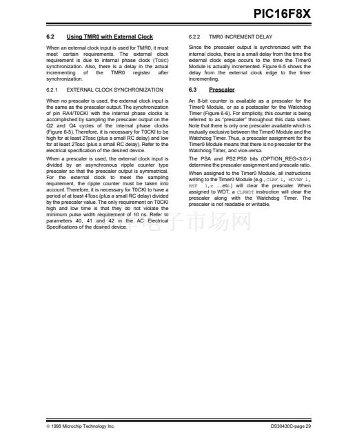
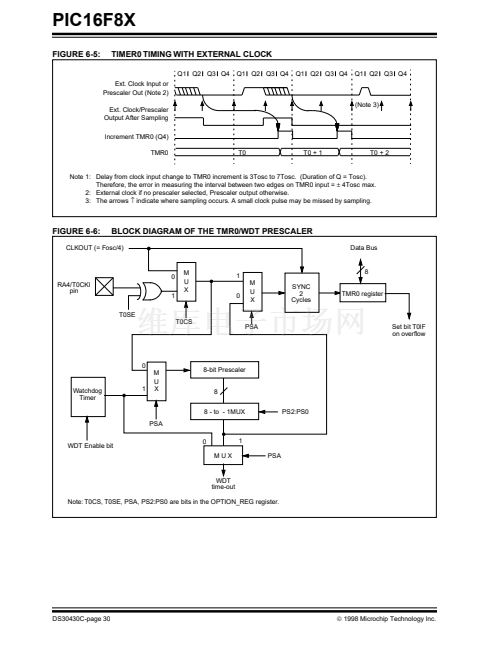
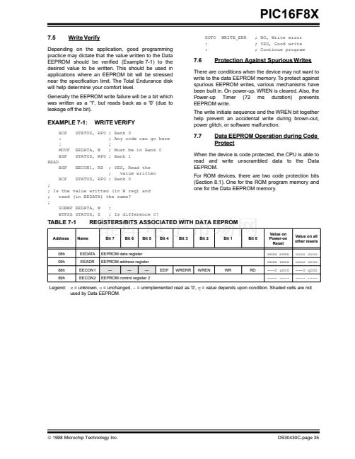
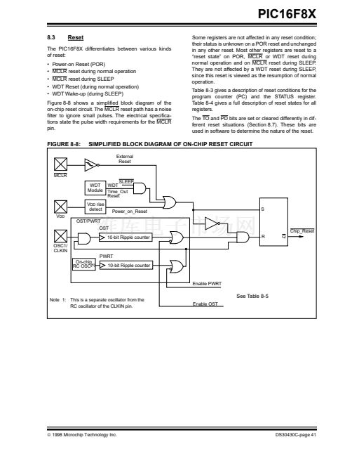
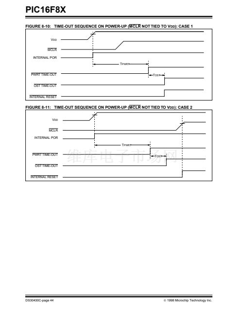
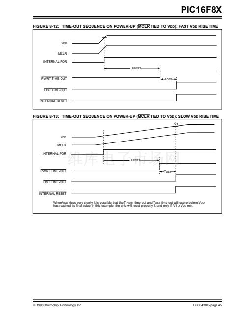
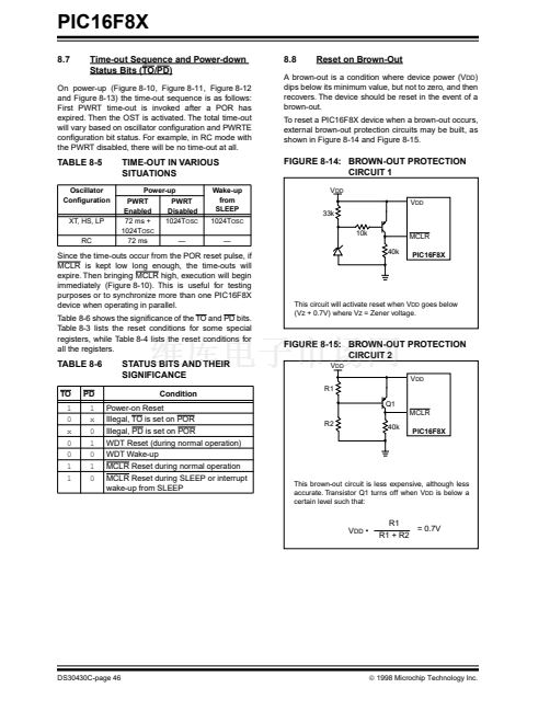
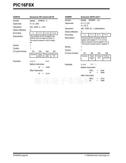
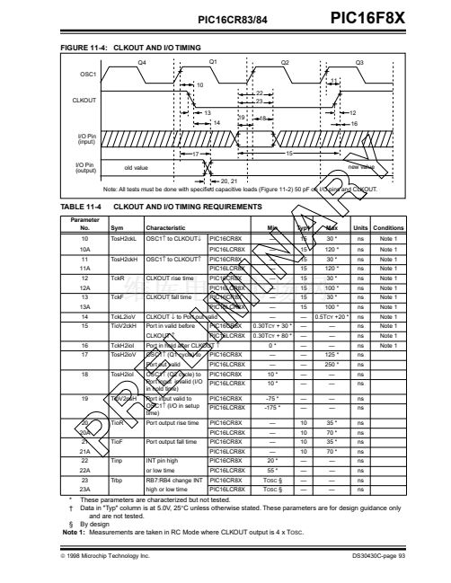
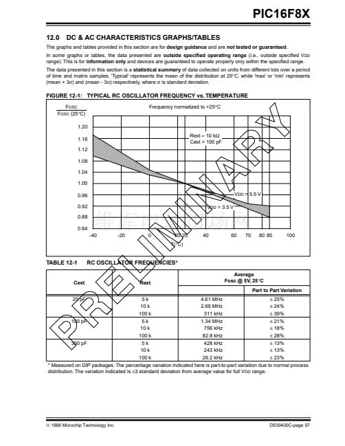
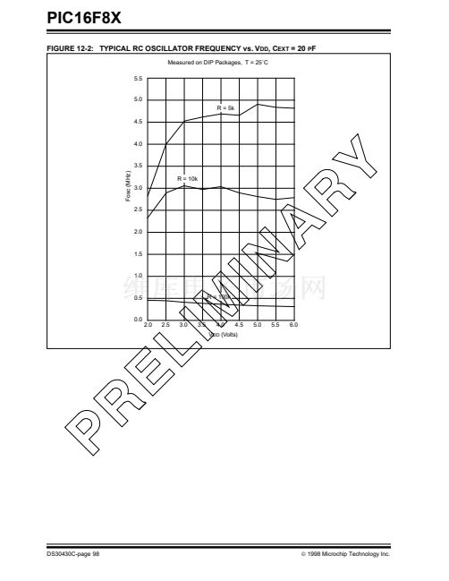
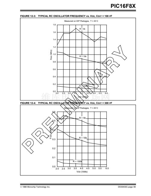
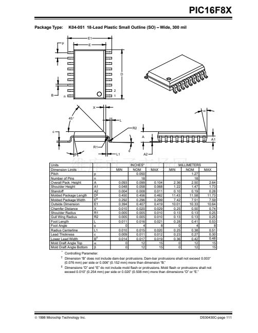
PIC16F8X
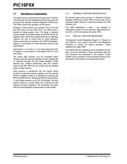
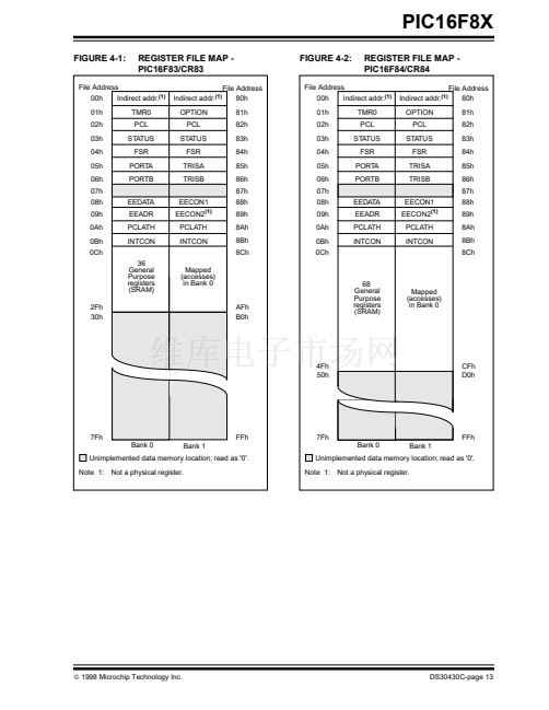
4.3
Program Counter: PCL and PCLATH
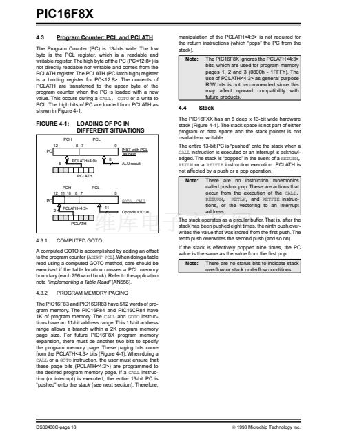
The Program Counter (PC) is 13-bits wide. The low
byte is the PCL register, which is a readable and
writable register. The high byte of the PC (PC<12:8>) is
not directly readable nor writable and comes from the
PCLATH register. The PCLATH (PC latch high) register
is a holding register for PC<12:8>. The contents of
PCLATH are transferred to the upper byte of the
program counter when the PC is loaded with a new
value. This occurs during a
CALL, GOTO
or a write to
PCL. The high bits of PC are loaded from PCLATH as
shown in Figure 4-1.
manipulation of the PCLATH<4:3> is not required for
the return instructions (which 鈥減ops鈥?the PC from the
stack).
Note:
The PIC16F8X ignores the PCLATH<4:3>
bits, which are used for program memory
pages 1, 2 and 3 (0800h - 1FFFh). The
use of PCLATH<4:3> as general purpose
R/W bits is not recommended since this
may affect upward compatibility with
future products.
4.4
Stack
FIGURE 4-1:
PCH
12
PC
5
LOADING OF PC IN
DIFFERENT SITUATIONS
PCL
8 7
0
INST with PCL
as dest
PCLATH<4:0>
8
ALU result
The PIC16FXX has an 8 deep x 13-bit wide hardware
stack (Figure 4-1). The stack space is not part of either
program or data space and the stack pointer is not
readable or writable.
The entire 13-bit PC is 鈥減ushed鈥?onto the stack when a
CALL
instruction is executed or an interrupt is acknowl-
edged. The stack is 鈥減opped鈥?in the event of a
RETURN,
RETLW
or a
RETFIE
instruction execution. PCLATH is
not affected by a push or a pop operation.
Note:
There are no instruction mnemonics
called push or pop. These are actions that
occur from the execution of the
CALL,
RETURN, RETLW,
and
RETFIE
instruc-
tions, or the vectoring to an interrupt
address.
PCLATH
PCH
12 11 10
PC
2
PCLATH<4:3>
11
Opcode <10:0>
PCL
8 7
0
GOTO, CALL
PCLATH
4.3.1
COMPUTED GOTO
The stack operates as a circular buffer. That is, after the
stack has been pushed eight times, the ninth push over-
writes the value that was stored from the 铿乺st push. The
tenth push overwrites the second push (and so on).
If the stack is effectively popped nine times, the PC
value is the same as the value from the 铿乺st pop.
Note:
There are no status bits to indicate stack
over铿俹w or stack under铿俹w conditions.
A computed GOTO is accomplished by adding an offset
to the program counter (ADDWF
PCL).
When doing a table
read using a computed GOTO method, care should be
exercised if the table location crosses a PCL memory
boundary (each 256 word block). Refer to the application
note
鈥淚mplementing a Table Read鈥?/div>
(AN556).
4.3.2
PROGRAM MEMORY PAGING
The PIC16F83 and PIC16CR83 have 512 words of pro-
gram memory. The PIC16F84 and PIC16CR84 have
1K of program memory. The
CALL
and
GOTO
instruc-
tions have an 11-bit address range. This 11-bit address
range allows a branch within a 2K program memory
page size. For future PIC16F8X program memory
expansion, there must be another two bits to specify
the program memory page. These paging bits come
from the PCLATH<4:3> bits (Figure 4-1). When doing a
CALL
or a
GOTO
instruction, the user must ensure that
these page bits (PCLATH<4:3>) are programmed to
the desired program memory page. If a
CALL
instruc-
tion (or interrupt) is executed, the entire 13-bit PC is
鈥減ushed鈥?onto the stack (see next section). Therefore,
DS30430C-page 18
漏
1998 Microchip Technology Inc.


 1
1
 2
2
 3
3
 4
4
 5
5
 6
6
 7
7
 8
8
 9
9
 10
10
 11
11
 12
12
 13
13
 14
14
 15
15
 16
16
 17
17
 18
18
 19
19
 20
20
 21
21
 22
22
 23
23
 24
24
 25
25
 26
26
 27
27
 28
28
 29
29
 30
30
 31
31
 32
32
 33
33
 34
34
 35
35
 36
36
 37
37
 38
38
 39
39
 40
40
 41
41
 42
42
 43
43
 44
44
 45
45
 46
46
 47
47
 48
48
 49
49
 50
50
 51
51
 52
52
 53
53
 54
54
 55
55
 56
56
 57
57
 58
58
 59
59
 60
60
 61
61
 62
62
 63
63
 64
64
 65
65
 66
66
 67
67
 68
68
 69
69
 70
70
 71
71
 72
72
 73
73
 74
74
 75
75
 76
76
 77
77
 78
78
 79
79
 80
80
 81
81
 82
82
 83
83
 84
84
 85
85
 86
86
 87
87
 88
88
 89
89
 90
90
 91
91
 92
92
 93
93
 94
94
 95
95
 96
96
 97
97
 98
98
 99
99
 100
100
 101
101
 102
102
 103
103
 104
104
 105
105
 106
106
 107
107
 108
108
 109
109
 110
110
 111
111
 112
112
 113
113
 114
114
 115
115
 116
116
 117
117
 118
118
 119
119
 120
120
 121
121
 122
122
 123
123
 124
124
