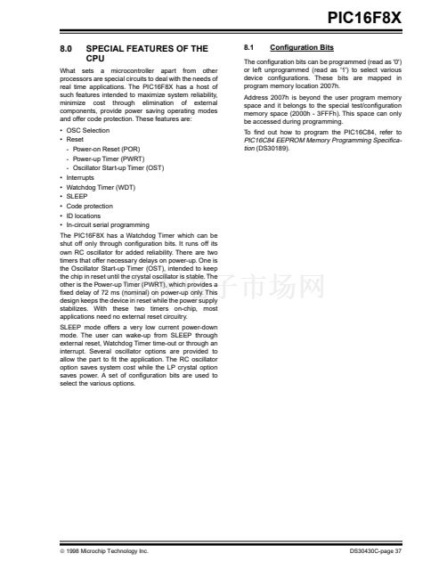
PIC16F8X
6.2
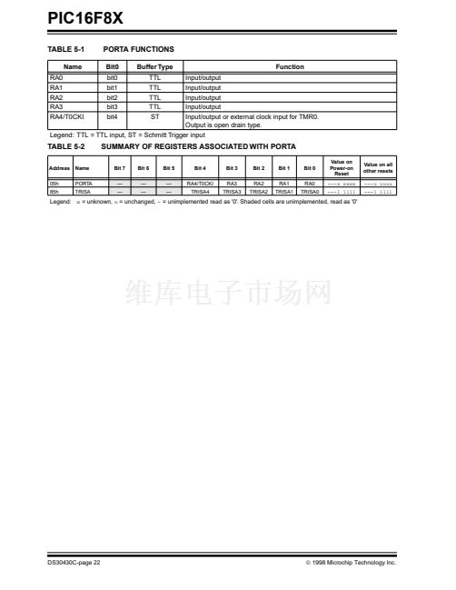
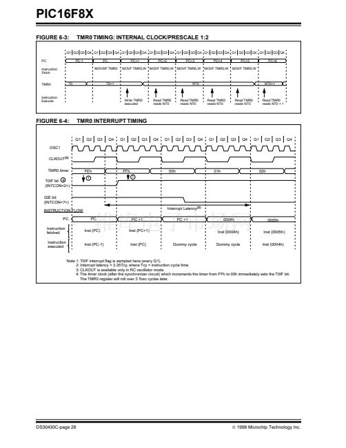
Using TMR0 with External Clock
6.2.2
TMR0 INCREMENT DELAY
When an external clock input is used for TMR0, it must
meet certain requirements. The external clock
requirement is due to internal phase clock (T
OSC
)
synchronization. Also, there is a delay in the actual
incrementing
of
the
TMR0
register
after
synchronization.
6.2.1
EXTERNAL CLOCK SYNCHRONIZATION
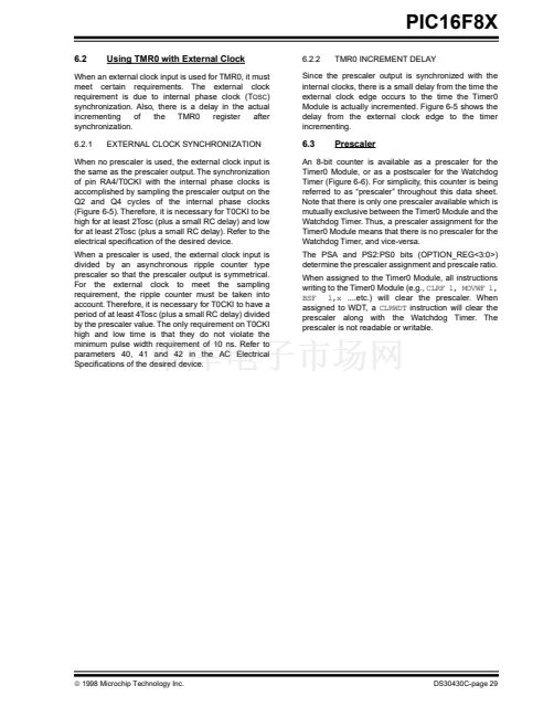
Since the prescaler output is synchronized with the
internal clocks, there is a small delay from the time the
external clock edge occurs to the time the Timer0
Module is actually incremented. Figure 6-5 shows the
delay from the external clock edge to the timer
incrementing.
6.3
Prescaler
When no prescaler is used, the external clock input is
the same as the prescaler output. The synchronization
of pin RA4/T0CKI with the internal phase clocks is
accomplished by sampling the prescaler output on the
Q2 and Q4 cycles of the internal phase clocks
(Figure 6-5). Therefore, it is necessary for T0CKI to be
high for at least 2Tosc (plus a small RC delay) and low
for at least 2Tosc (plus a small RC delay). Refer to the
electrical speci铿乧ation of the desired device.
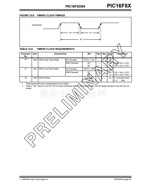
When a prescaler is used, the external clock input is
divided by an asynchronous ripple counter type
prescaler so that the prescaler output is symmetrical.
For the external clock to meet the sampling
requirement, the ripple counter must be taken into
account. Therefore, it is necessary for T0CKI to have a
period of at least 4Tosc (plus a small RC delay) divided
by the prescaler value. The only requirement on T0CKI
high and low time is that they do not violate the
minimum pulse width requirement of 10 ns. Refer to
parameters 40, 41 and 42 in the AC Electrical
Speci铿乧ations of the desired device.
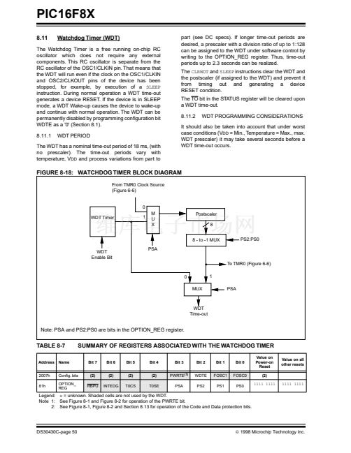
An 8-bit counter is available as a prescaler for the
Timer0 Module, or as a postscaler for the Watchdog
Timer (Figure 6-6). For simplicity, this counter is being
referred to as 鈥減rescaler鈥?throughout this data sheet.
Note that there is only one prescaler available which is
mutually exclusive between the Timer0 Module and the
Watchdog Timer. Thus, a prescaler assignment for the
Timer0 Module means that there is no prescaler for the
Watchdog Timer, and vice-versa.
The PSA and PS2:PS0 bits (OPTION_REG<3:0>)
determine the prescaler assignment and prescale ratio.
When assigned to the Timer0 Module, all instructions
writing to the Timer0 Module (e.g.,
CLRF 1, MOVWF 1,
BSF 1,x
....etc.) will clear the prescaler. When
assigned to WDT, a
CLRWDT
instruction will clear the
prescaler along with the Watchdog Timer. The
prescaler is not readable or writable.
漏
1998 Microchip Technology Inc.
DS30430C-page 29


 1
1
 2
2
 3
3
 4
4
 5
5
 6
6
 7
7
 8
8
 9
9
 10
10
 11
11
 12
12
 13
13
 14
14
 15
15
 16
16
 17
17
 18
18
 19
19
 20
20
 21
21
 22
22
 23
23
 24
24
 25
25
 26
26
 27
27
 28
28
 29
29
 30
30
 31
31
 32
32
 33
33
 34
34
 35
35
 36
36
 37
37
 38
38
 39
39
 40
40
 41
41
 42
42
 43
43
 44
44
 45
45
 46
46
 47
47
 48
48
 49
49
 50
50
 51
51
 52
52
 53
53
 54
54
 55
55
 56
56
 57
57
 58
58
 59
59
 60
60
 61
61
 62
62
 63
63
 64
64
 65
65
 66
66
 67
67
 68
68
 69
69
 70
70
 71
71
 72
72
 73
73
 74
74
 75
75
 76
76
 77
77
 78
78
 79
79
 80
80
 81
81
 82
82
 83
83
 84
84
 85
85
 86
86
 87
87
 88
88
 89
89
 90
90
 91
91
 92
92
 93
93
 94
94
 95
95
 96
96
 97
97
 98
98
 99
99
 100
100
 101
101
 102
102
 103
103
 104
104
 105
105
 106
106
 107
107
 108
108
 109
109
 110
110
 111
111
 112
112
 113
113
 114
114
 115
115
 116
116
 117
117
 118
118
 119
119
 120
120
 121
121
 122
122
 123
123
 124
124
