Philips Semiconductors
SC16C754
Quad UART with 64-byte FIFO
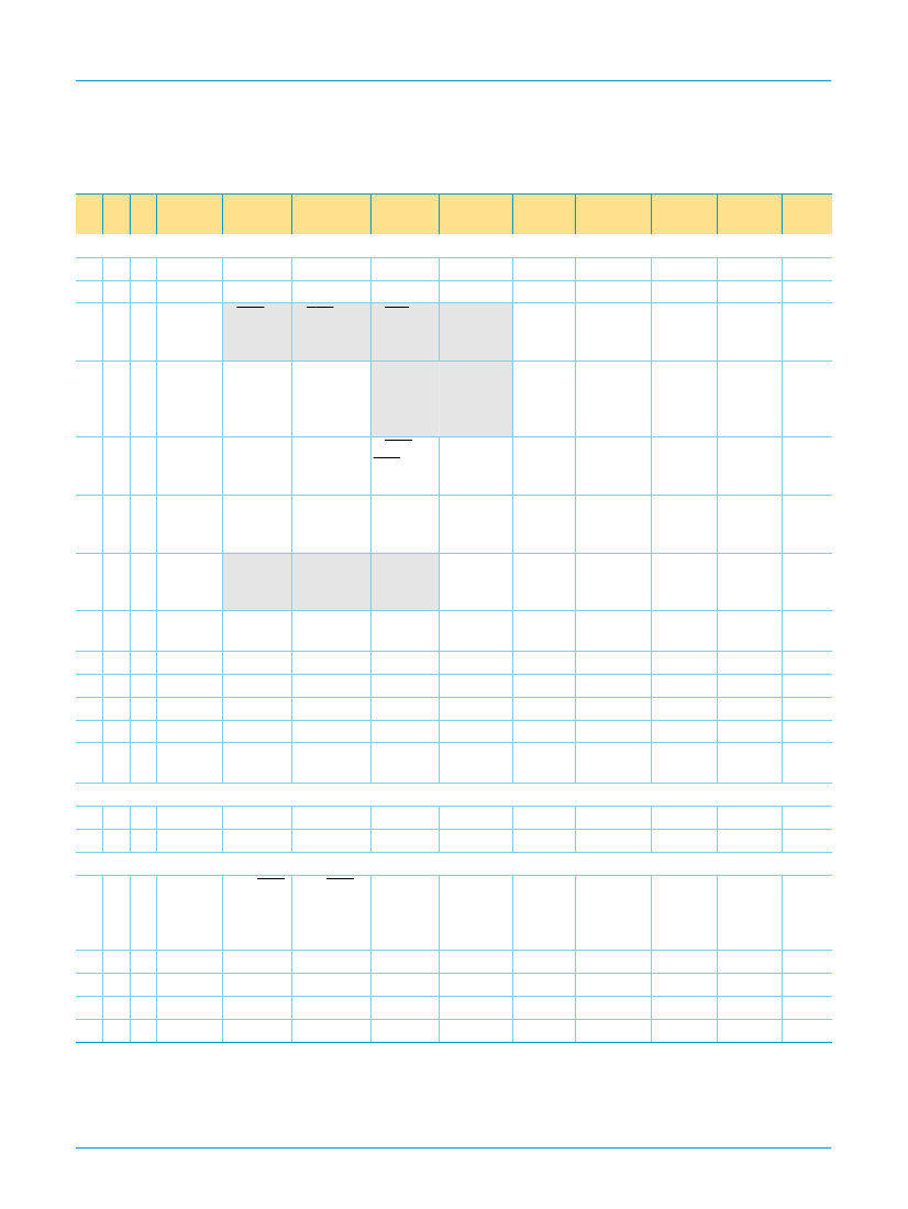
Table 10
lists and describes the SC16C754 internal registers.
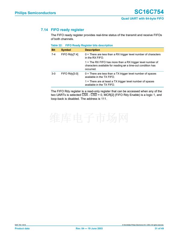
Table 10:
SC16C754 internal registers
Bit 6
Bit 5
Bit 4
Bit 3
Bit 2
Bit 1
Bit 0
Read/
Write
R
W
A2 A1 A0 Register Bit 7
General Register Set
[1]
0
0
0
0
0
0
0
0
1
RHR
THR
IER
bit 7
bit 7
0/CTS
interrupt
enable
[2]
RX
trigger
level
(MSB)
FCR[0]
bit 6
bit 6
0/RTS
interrupt
enable
[2]
bit 5
bit 5
0/Xoff
[2]
bit 4
bit 4
0/X sleep
mode
[2]
0/TX
trigger
level
(LSB)
[2]
0/Xoff
bit 3
bit 3
bit 2
bit 2
bit 1
bit 1
THR
empty
interrupt
bit 0
bit 0
modem receive
status
line status
interrupt interrupt
DMA
mode
select
TX FIFO
reset
Rx data R/W
available
interrupt
W
0
1
0
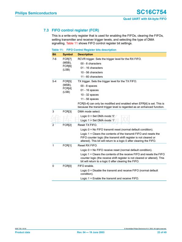
FCR
RX trigger 0/TX
level (LSB) trigger
level
(MSB)
[2]
FCR[0]
0/CTS,
RTS
RX FIFO FIFO
reset
enable
0
1
0
IIR
interrupt interrupt
priority
priority
bit 2
bit 1
number of
stop bits
FIFO
ready
enable
interrupt
priority
bit 0
word
length
bit 1
RTS
interrupt R
status
word
length
bit 0
DTR
R/W
0
1
1
LCR
DLAB
break
control bit
TCR and
TLR
enable
set parity parity type parity
select
enable
0/Xon
Any
0/enable IRQ
loop-back enable
OP
break
interrupt
CTS
bit 4
bit 4
bit 4
RX FIFO
A status
bit 4
bit 12
framing
error
鈭咰D
bit 3
bit 3
bit 3
0
1
0
0
MCR
1脳 or
1脳/4
clock
0/error in
RX FIFO
CD
bit 7
bit 7
bit 7
0
R/W
1
1
1
1
1
1
0
1
1
1
1
1
1
0
1
0
1
1
LSR
MSR
SPR
TCR
TLR
FIFO
Rdy
DLL
DLH
EFR
THR and
THR
TSR empty empty
RI
bit 6
bit 6
bit 6
0
DSR
bit 5
bit 5
bit 5
RX FIFO
B status
bit 5
bit 13
parity error overrun
error
鈭哛I
bit 2
bit 2
bit 2
0
鈭咲SR
bit 1
bit 1
bit 1
data in
receiver
鈭咰TS
bit 0
bit 0
bit 0
R
R
R/W
R/W
R/W
TX FIFO TX FIFO R
B status A status
bit 1
bit 9
software
铿俹w
control
bit 1
bit 1
bit 1
bit 1
bit 1
bit 0
bit 8
R/W
R/W
Special Register Set
[3]
0
0
0
0
0
1
0
1
0
bit 7
bit 15
bit 6
bit 14
bit 3
bit 11
bit 2
bit 10
Enhanced Register Set
[4]
Auto CTS Auto RTS
Special
Enable
software software
character enhanced 铿俹w
铿俹w
detect
functions control
control
[2]
bit 3
bit 2
bit 5
bit 5
bit 5
bit 5
bit 4
bit 4
bit 4
bit 4
bit 3
bit 3
bit 3
bit 3
bit 2
bit 2
bit 2
bit 2
software R/W
铿俹w
control
bit 0
bit 0
bit 0
bit 0
bit 0
R/W
R/W
R/W
R/W
1
1
1
1
[1]
[2]
[3]
[4]
0
0
1
1
0
1
0
1
Xon1
Xon2
Xoff1
Xoff2
bit 7
bit 7
bit 7
bit 7
bit 6
bit 6
bit 6
bit 6
These registers are accessible only when LCR[7] = 0.
The shaded bits in the above table can only be modi铿乪d if register bit EFR[4] is enabled, i.e., if enhanced functions are enabled.
The Special Register set is accessible only when LCR[7] is set to a logic 1.
Enhanced Feature Register; Xon-1,2 and Xoff-1,2 are accessible only when LCR is set to 鈥楤F
Hex
鈥?
漏 Koninklijke Philips Electronics N.V. 2003. All rights reserved.
9397 750 11618
Product data
Rev. 04 鈥?19 June 2003
21 of 49


 1
1
 2
2
 3
3
 4
4
 5
5
 6
6
 7
7
 8
8
 9
9
 10
10
 11
11
 12
12
 13
13
 14
14
 15
15
 16
16
 17
17
 18
18
 19
19
 20
20
 21
21
 22
22
 23
23
 24
24
 25
25
 26
26
 27
27
 28
28
 29
29
 30
30
 31
31
 32
32
 33
33
 34
34
 35
35
 36
36
 37
37
 38
38
 39
39
 40
40
 41
41
 42
42
 43
43
 44
44
 45
45
 46
46
 47
47
 48
48
 49
49
