Philips Semiconductors
SC16C754
Quad UART with 64-byte FIFO
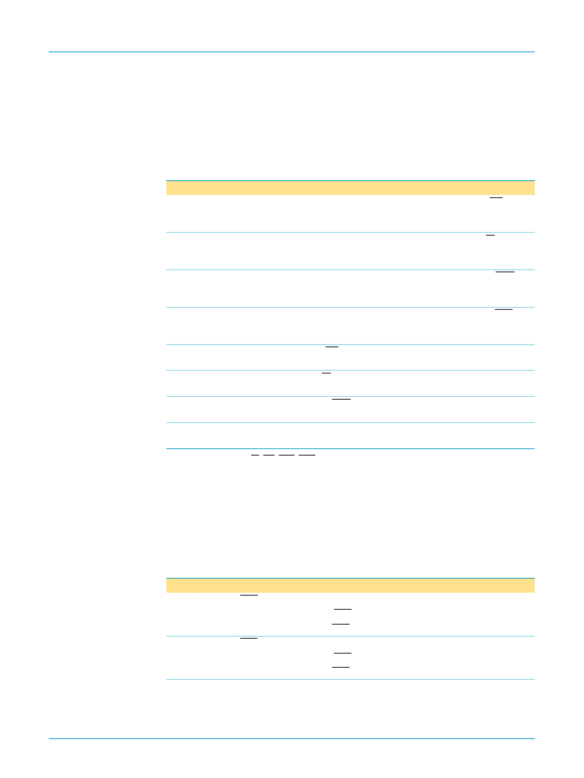
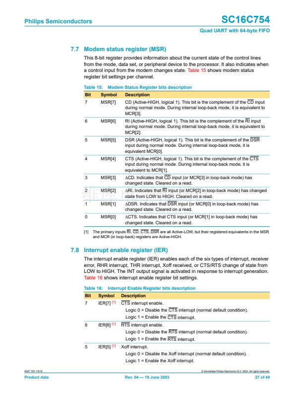
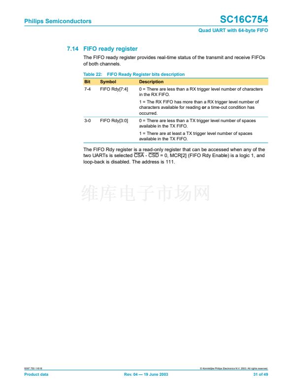
7.7 Modem status register (MSR)
This 8-bit register provides information about the current state of the control lines
from the mode, data set, or peripheral device to the processor. It also indicates when
a control input from the modem changes state.
Table 15
shows modem status
register bit settings per channel.
Table 15:
Bit
7
Modem Status Register bits description
Description
CD (Active-HIGH, logical 1). This bit is the complement of the CD input
during normal mode. During internal loop-back mode, it is equivalent to
MCR[3].
RI (Active-HIGH, logical 1). This bit is the complement of the RI input
during normal mode. During internal loop-back mode, it is equivalent to
MCR[2].
DSR (Active-HIGH, logical 1). This bit is the complement of the DSR
input during normal mode. During internal loop-back mode, it is
equivalent MCR[0].
CTS (Active-HIGH, logical 1). This bit is the complement of the CTS
input during normal mode. During internal loop-back mode, it is
equivalent to MCR[1].
鈭咰D.
Indicates that CD input (or MCR[3] in loop-back mode) has
changed state. Cleared on a read.
鈭哛I.
Indicates that RI input (or MCR[2] in loop-back mode) has changed
state from LOW to HIGH. Cleared on a read.
鈭咲SR.
Indicates that DSR input (or MCR[0] in loop-back mode) has
changed state. Cleared on a read.
鈭咰TS.
Indicates that CTS input (or MCR[1] in loop-back mode) has
changed state. Cleared on a read.
Symbol
MSR[7]
6
MSR[6]
5
MSR[5]
4
MSR[4]
3
2
1
0
[1]
MSR[3]
MSR[2]
MSR[1]
MSR[0]
The primary inputs RI, CD, CTS, DSR are all Active-LOW, but their registered equivalents in the MSR
and MCR (in loop-back) registers are Active-HIGH.
7.8 Interrupt enable register (IER)
The interrupt enable register (IER) enables each of the six types of interrupt, receiver
error, RHR interrupt, THR interrupt, Xoff received, or CTS/RTS change of state from
LOW to HIGH. The INT output signal is activated in response to interrupt generation.
Table 16
shows interrupt enable register bit settings.
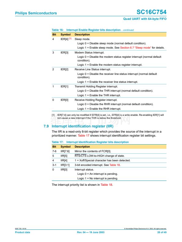
Table 16:
Bit
7
Interrupt Enable Register bits description
Description
CTS interrupt enable.
Logic 0 = Disable the CTS interrupt (normal default condition).
Logic 1 = Enable the CTS interrupt.
6
IER[6]
[1]
RTS interrupt enable.
Logic 0 = Disable the RTS interrupt (normal default condition).
Logic 1 = Enable the RTS interrupt.
5
IER[5]
[1]
Xoff interrupt.
Logic 0 = Disable the Xoff interrupt (normal default condition).
Logic 1 = Enable the Xoff interrupt.
9397 750 11618
漏 Koninklijke Philips Electronics N.V. 2003. All rights reserved.
Symbol
IER[7]
[1]
Product data
Rev. 04 鈥?19 June 2003
27 of 49


 1
1
 2
2
 3
3
 4
4
 5
5
 6
6
 7
7
 8
8
 9
9
 10
10
 11
11
 12
12
 13
13
 14
14
 15
15
 16
16
 17
17
 18
18
 19
19
 20
20
 21
21
 22
22
 23
23
 24
24
 25
25
 26
26
 27
27
 28
28
 29
29
 30
30
 31
31
 32
32
 33
33
 34
34
 35
35
 36
36
 37
37
 38
38
 39
39
 40
40
 41
41
 42
42
 43
43
 44
44
 45
45
 46
46
 47
47
 48
48
 49
49
